
Surgical sealing apparatus

a sealing apparatus and surgical technology, applied in the field of sealing apparatus and methods, can solve problems such as the inability to accommodate the wide range of instruments

Inactive Publication Date: 2004-10-14
TYCO HEALTHCARE GRP LP
View PDF99 Cites 139 Cited by
  • Summary
  • Abstract
  • Description
  • Claims
  • Application Information

AI Technical Summary

Benefits of technology

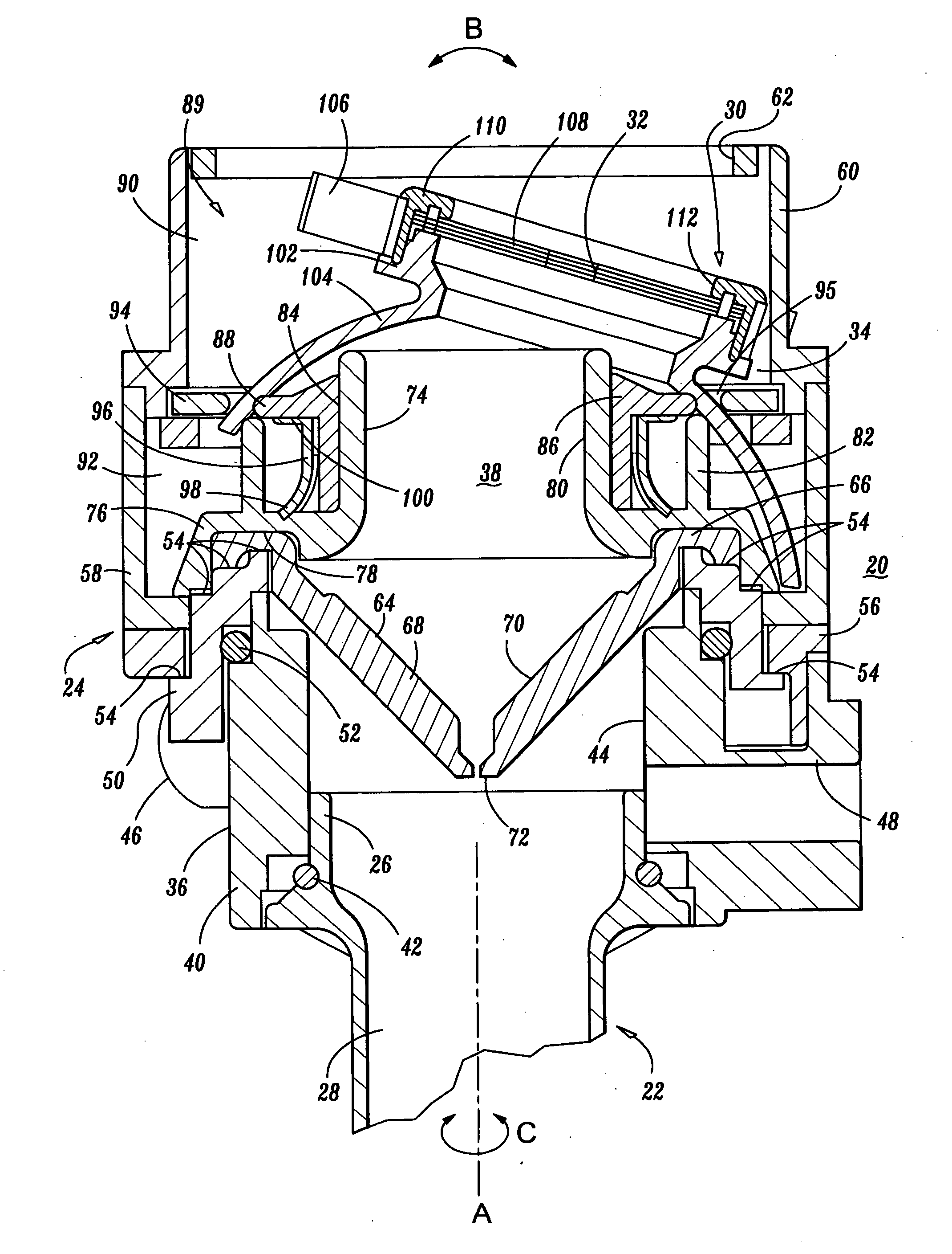
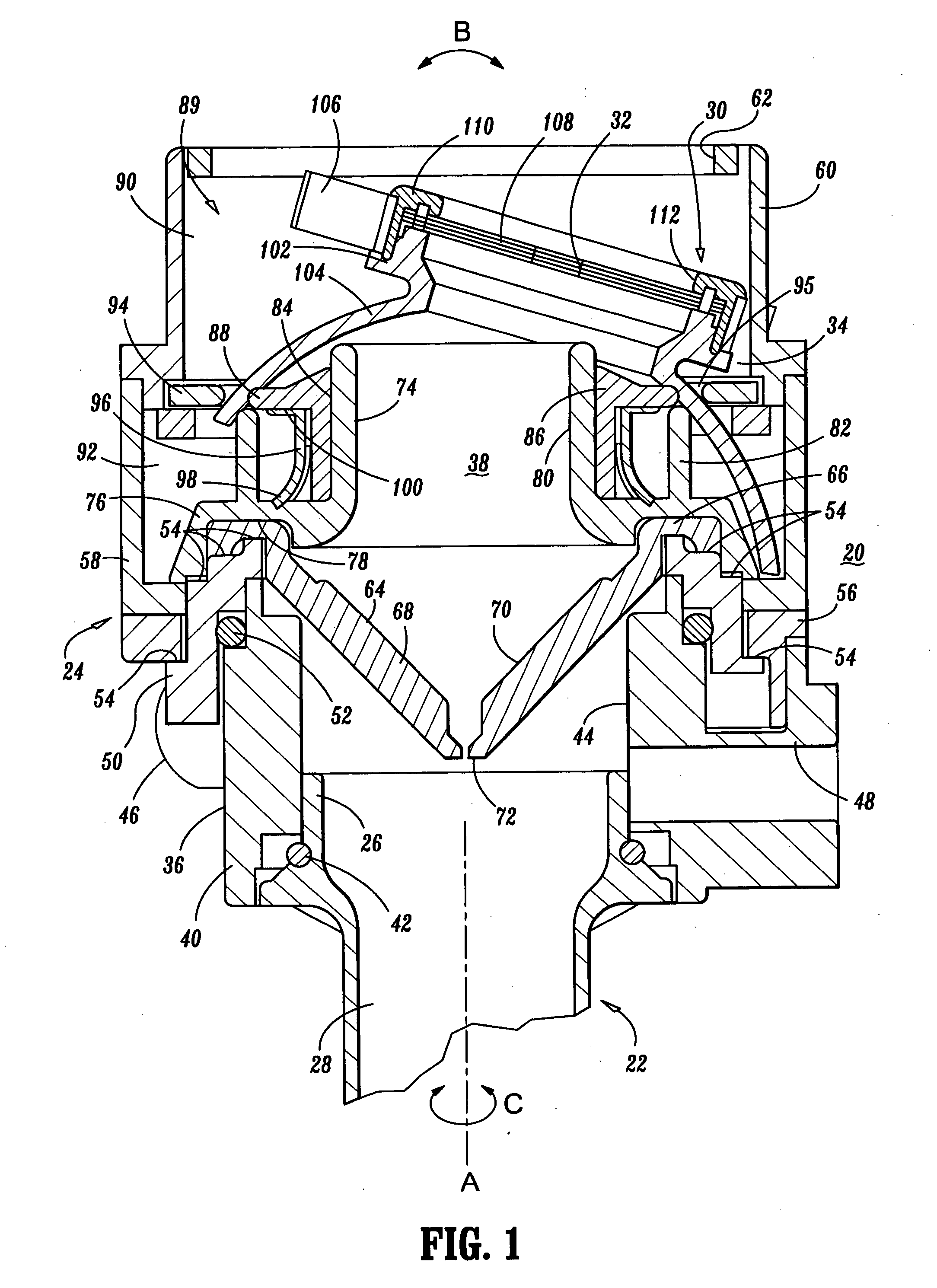
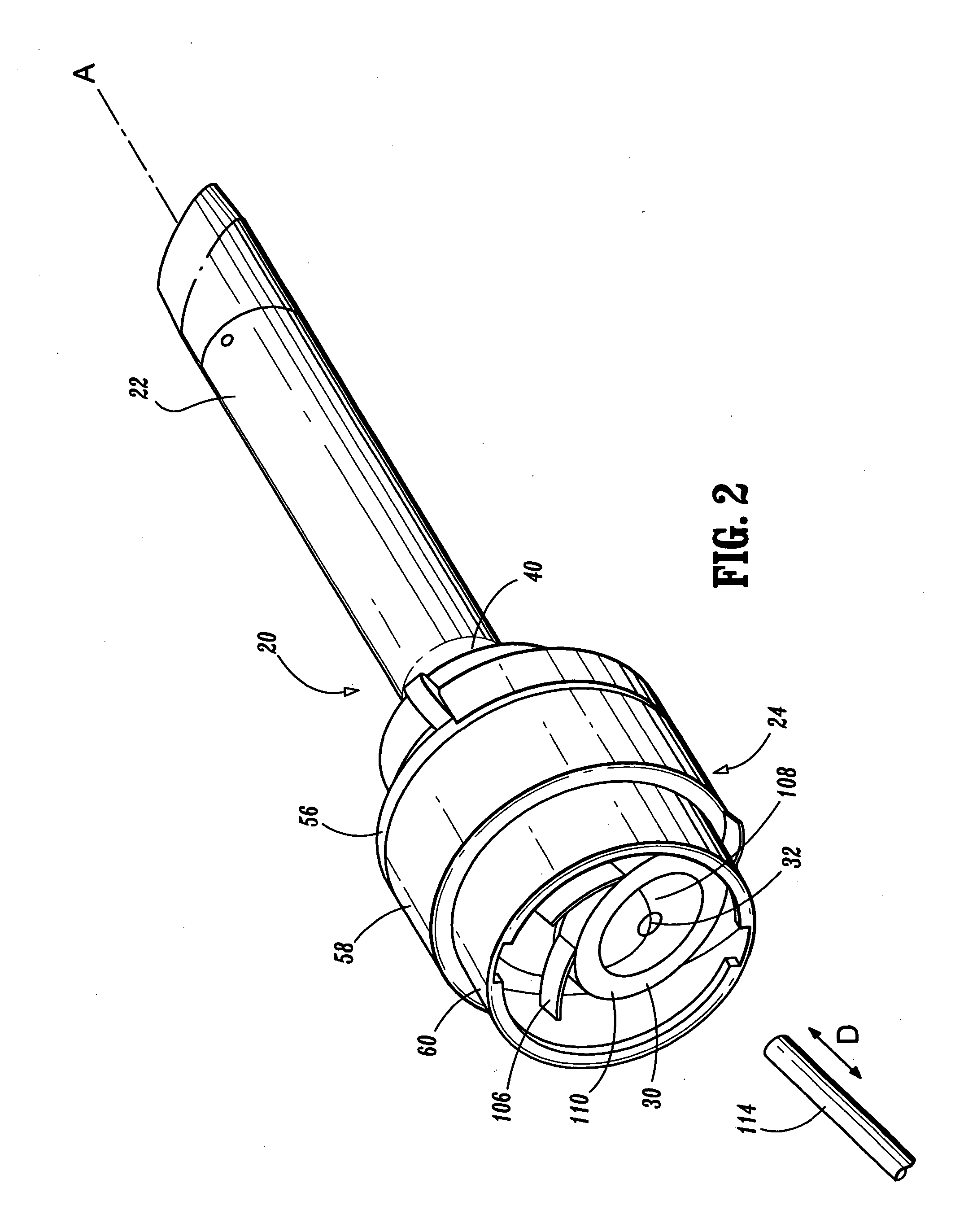
[0027] It is contemplated that sealing apparatus 20 is detachably mountable to proximal end 26 of cannula 22. Thus, the surgeon can remove components of sealing apparatus 20 from cannula 22 at any time during the surgical procedure and, similarly, mount sealing apparatus 20 to cannula 22 when desired to provide a sealing engagement with instrumentation to be inserted through cannula 22. In addition, sealing apparatus 20 may be readily adapted for mounting to conventional cannulas of different structures. The detachability of sealing apparatus 20 from cannula 22 facilitates specimen removal through cannula 22 and reduces the profile of cannula 22 when sealing apparatus 20 is not needed for the surgical procedure.
[0047] Flexible seal 108 is sufficiently resilient to accommodate and provide a fluid tight seal with instruments of varying diameters. The tip of surgical instrument 114 is caused to engage and pass through cavity 32 stretching flexible seal 108 distally while also permitting relatively easy passage of surgical instrument 114 through sealing apparatus 20. Flexible seal 108 engages surgical instrument 114 to form a substantially fluid tight seal about surgical instrument 114 as it passes therethrough. Surgical instrument 114 is further advanced through sealing apparatus 20 to sealing valve 64 whereby contact region 72 forms a substantial seal with instrument 114.

Problems solved by technology

A difficulty encountered is the capability of accommodating the wide range of instrumentation and the angle and orientation from which the instrumentation is introduced and ultimately used.

Method used


Image

  • Surgical sealing apparatus
  • Surgical sealing apparatus
  • Surgical sealing apparatus

Examples


Embodiment Construction

[0023] In the following description, as is traditional, the term "proximal" refers to the portion of the instrument closest to the operator while the term "distal" refers to the portion of the instrument remote from the operator.

[0024] Referring initially to FIGS. 1 and 2, there is illustrated a sealing apparatus 20 constructed in accordance with the principles of the present disclosure which includes an elongate shaft, such as, for example, a cannula 22 of a cannula assembly. Sealing apparatus 20 contemplates the introduction and manipulation of various types of instrumentation adapted for insertion through a trocar and / or cannula assembly while maintaining a fluid tight interface about the instrumentation to preserve the atmospheric integrity of a surgical procedure from gas and / or fluid leakage. This feature of the present disclosure advantageously ensures that gases and / or fluids do not enter or exit a body cavity. Examples of such instrumentation include clip appliers, graspers...


PUM


Abstract

A sealing apparatus is disclosed that includes a housing that is mountable to an elongate shaft which includes an axial lumen. A sealing member defines a cavity and has at least a portion thereof disposed within the housing. The cavity is spherically moveable relative to the elongate shaft. The housing may define a passageway communicating with the cavity and the axial lumen. An inner surface of the housing can define at least a portion of a pathway configured for movement of the sealing member. The sealing member may include an end portion defining a moveable limit within the pathway. The sealing member may be fixedly mounted to a portion of the housing such that the cavity and the portion of the housing are correspondingly spherically moveable relative the elongate shaft. A sealing element having at least a portion disposed within the housing may moveably support the sealing member. The sealing element may cooperate with an inner surface of the housing to define at least a portion of the pathway. The sealing element may include a resilient portion configured to bias the sealing member relative to a longitudinal axis of the elongate shaft. The sealing member can be biased to a centered position relative to the longitudinal axis and in substantially coaxial alignment therewith. In an alternate embodiment, the sealing member is mounted to the housing and the housing may be configured for substantially spherical movement relative to the elongate shaft and / or substantially lateral movement relative to the longitudinal axis of the elongate shaft.

Description

[0001] 1. Technical Field[0002] The present disclosure relates generally to a sealing apparatus and methods that facilitate percutaneous access of surgical instruments into a patient's body, and more particularly, to a sealing apparatus that movably accommodates instrumentation while maintaining a gas and / or fluid tight seal therewith.[0003] 2. Background of Related Art[0004] Minimally invasive and laparoscopic procedures generally require that any instrumentation inserted into the body is sealed, i.e., provisions must be made to ensure that gases and / or fluids do not enter or exit the body through an endoscopic incision, such as, for example, in surgical procedures having the surgical region insufflated. For such procedures, the introduction of a tube into certain anatomical cavities, such as the abdominal cavity, is usually accomplished by use of a system incorporating a trocar and cannula assembly. Since the cannula is in direct communication with the internal portion of the seal...

Claims


Application Information

Patent Timeline
IPC IPC(8): A61B17/34
CPCA61B17/3462A61B17/3498
Inventor SMITH, ROBERT C.
Owner TYCO HEALTHCARE GRP LP
Learn More