

Sealing structure for a fuel cell, as well as a method for producing it, and a fuel cell with the sealing structure
a technology of sealing structure and fuel cell, which is applied in the direction of cell components, final product manufacturing, sustainable manufacturing/processing, etc., can solve the problems of reducing the electrical resistance of the sealing material, the failure of the sealing effect, and the inability to meet the requirements of the application
- Summary
- Abstract
- Description
- Claims
- Application Information
AI Technical Summary
Problems solved by technology
Method used
Image

Examples
Embodiment Construction
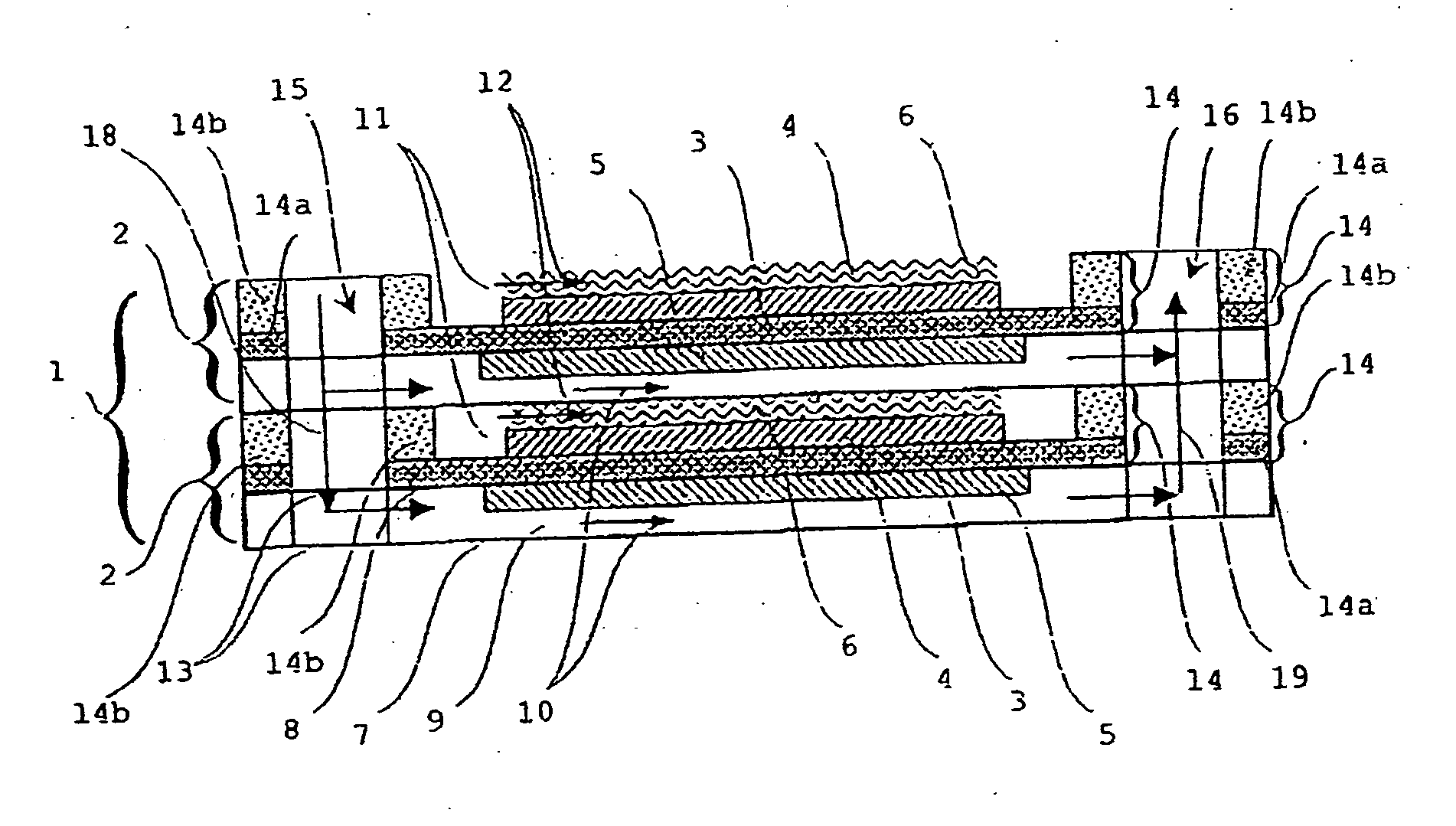
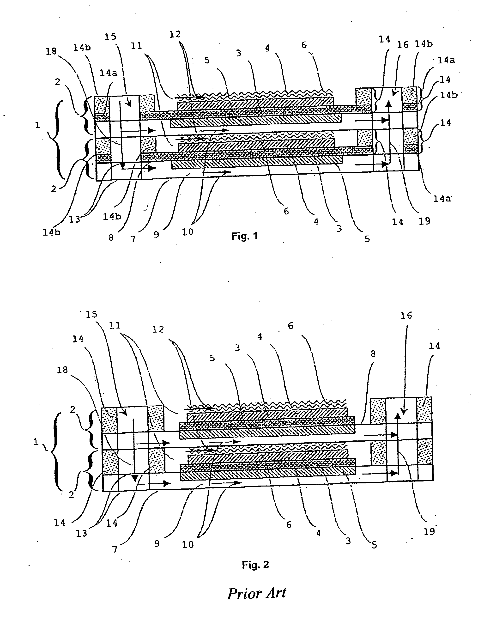
[0023] A sealing structure 14a, 14b in accordance with the invention is suitable for a fuel cell stack 1 in accordance with the invention represented in FIG. 1, including individual fuel cells 2 embodied as high-temperature fuel cells, in particular as solid electrolyte fuel cells (SOFCs), having an electrolyte layer 3, a cathode layer 4 and a anode layer 5. The electrically effective layers 3, 4, 5 are possibly arranged on a porous metallic substrate layer (not represented), which is preferably embodied as a mechanically supporting layer. Moreover, combustion gas can reach the anode 5 through the porous metallic substrate layer. The porous metallic substrate layer is embodied, for example, as a nickelous felt element or as FeCrAlY foam. The anode layer consists, for example, of a nickel / yttrium-stabilized zirconium dioxide (Ni--YSZ) cermet material, the electrolyte layer 3 is embodied to be oxygen-conducting and consists, for example, of Y.sub.2O.sub.3-stabilized zirconium oxide an...
PUM
 Abstract
Description
Claims
Application Information