Male/female tool coupling for rotary tools

a technology of rotary tools and tool couplings, which is applied in the direction of manufacturing tools, mechanical equipment, transportation and packaging, etc., can solve the problem that the stop face does not provide any guiding in the radial direction of the tool coupling

Inactive Publication Date: 2004-10-28
SANDVIK INTELLECTUAL PROPERTY AB
View PDF18 Cites 17 Cited by
  • Summary
  • Abstract
  • Description
  • Claims
  • Application Information

AI Technical Summary

Benefits of technology

[0005] A primary object of the present invention is to provide a tool coupling of the kind defined by way of introduction, which coupling is free of play.
[0008] At least the primary object of the present invention is realized by means of a rotary tool comprising first and second tool holders together defining a center axis and being clamped together in an axial direction by a force-applying member. The first tool body includes an axially extending male part and the second tool body includes an axially extending female part in which the male part is received. First and second guiding structures are provided for guiding the first and second tool bodies relative to one another in the radial direction. The first guiding structure includes radially outer interengaging guide surfaces disposed on the first and second tool bodies at a location adjacent outer circumferences thereof. The second guide structure includes radially inner interengaging guide surfaces connected to the male and female parts, respectively.

Problems solved by technology

These stop faces do not provide any guiding in the radial direction of the tool coupling.

Method used


Image

  • Male/female tool coupling for rotary tools
  • Male/female tool coupling for rotary tools
  • Male/female tool coupling for rotary tools

Examples


Embodiment Construction

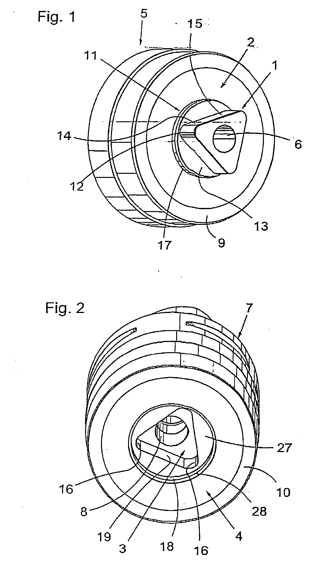
[0015] The embodiment of a tool coupling according to the present invention illustrated in FIGS. 1 and 2 comprises a male part 1, see FIG. 1, and a female part 3, see FIG. 2. The male part 1 is arranged on a first contact or end surface 2 of a first tool body 5 and the female part 3 is formed in a second contact or end surface 4 of a second tool body 7. The first tool body 5 may, for instance, consist of a cutter head while the second tool body 7, for instance, may consist of an extender or the like. At the end facing away from the female part 3, the second tool body 7 may be provided with some other type of tool coupling, for instance the tool coupling CAPTO.RTM., marketed by AB Sandvik Coromant. The tool bodies 5 and 7 are only shown schematically in the present patent application.

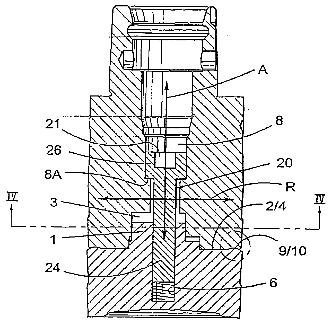
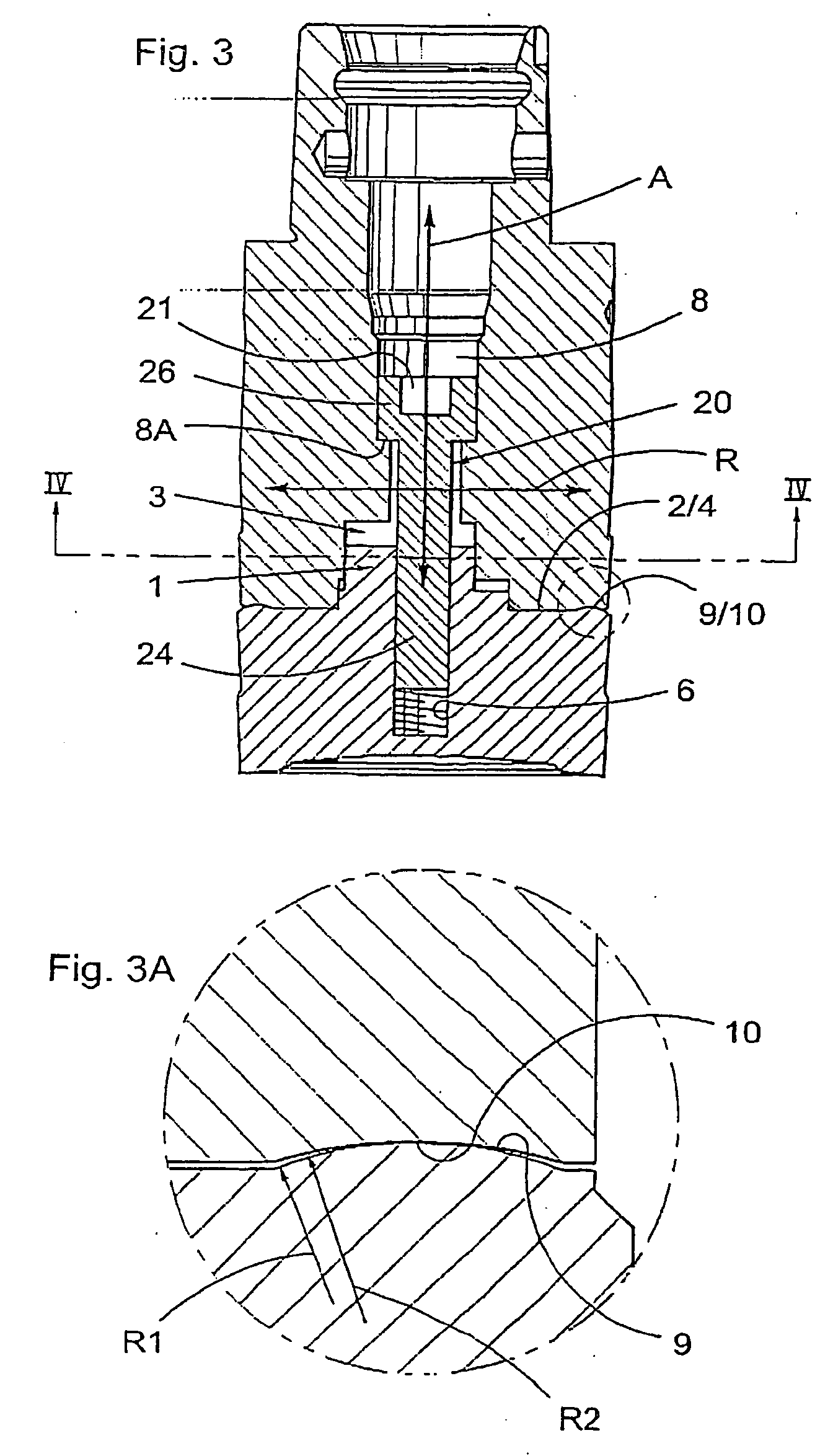
[0016] In the illustrated embodiment, an axial first center hole 6 extends through a part of the first tool body 5 and an axial second center hole 8 extends through the second tool body 7. The first cent...


PUM

PropertyMeasurementUnit
circumferencesaaaaaaaaaa
radius of curvatureaaaaaaaaaa
shapeaaaaaaaaaa

Abstract

A rotary tool includes first and second tool bodies defining an axis and clamped together in the axial direction by a screw. The tool bodies include axially extending male and female parts that engage one another to transmit rotary force. Spaced radially outwardly of the male and female parts are two sets of radial guiding structures for guiding the tool bodies in the radial direction, so a radial play can exist between the male and female parts.

Description

[0001] This application claims priority from Patent Application Serial No. 0300197-1 filed in Sweden on Jan. 28, 2003, the entire content of which is hereby incorporated by reference.[0002] The present invention relates to a tool coupling for rotary tools for chip removing machining, which tool coupling is intended to interconnect a first tool body and a second tool body. The tool coupling comprises a male part arranged on the first tool body and a female part arranged on the second tool body, the male part and the female part being intended to be in engagement with each other in an operative state of the tool coupling. The tool coupling comprises members for applying an axial, uniting force to the male part and the female part.PRIOR ART[0003] From Swedish Patent 457,623 (corresponding to Andersson et al. U.S. Pat. No. 4,834,597), a tool coupling is previously known where a male part interacts with a female part, the same being conical and having non-circular cross-sections. In the ...

Claims


Application Information

Patent Timeline
Patent Type & Authority Applications(United States)
IPC IPC(8): B23B31/00B23B31/11
CPCB23B31/008B23B31/11B23C2265/32Y10T409/30952Y10T409/309408Y10T279/16Y10T409/3098B23B51/00B23C5/26
Inventor PANTZAR, GORAN
Owner SANDVIK INTELLECTUAL PROPERTY AB
Why Eureka
Try Eureka