Power supply based audio compression for digital audio amplifier

a technology of power supply and audio compression, applied in the direction of amplifier modification, volume compression/expansion, code conversion, etc., can solve the problem that the power supply cannot provide the same specified power to multiple channels at the same time or to a single channel over a longer period of time, the power supply operation is less than, and the technique may fail to compensate if the power supply is not provided

Inactive Publication Date: 2004-11-11
CIRRUS LOGIC INC
View PDF8 Cites 22 Cited by
  • Summary
  • Abstract
  • Description
  • Claims
  • Application Information

AI Technical Summary

Problems solved by technology

However, the same power supply may not be capable of providing the same specified power to multiple channels at the same time or to a single channel over a longer period of time.
In other instances, the load may change causing the power supply to operate at less than the fully-rated voltage.
Although this compensating technique adjusts for non-constant power supply voltages under slow changing conditions, the technique may fail to compensate if the power supply is under-rated or if certain operating parameter of the power supply is exceeded.
The clipping of the output results in distortion.

Method used


Image

  • Power supply based audio compression for digital audio amplifier
  • Power supply based audio compression for digital audio amplifier
  • Power supply based audio compression for digital audio amplifier

Examples


Embodiment Construction

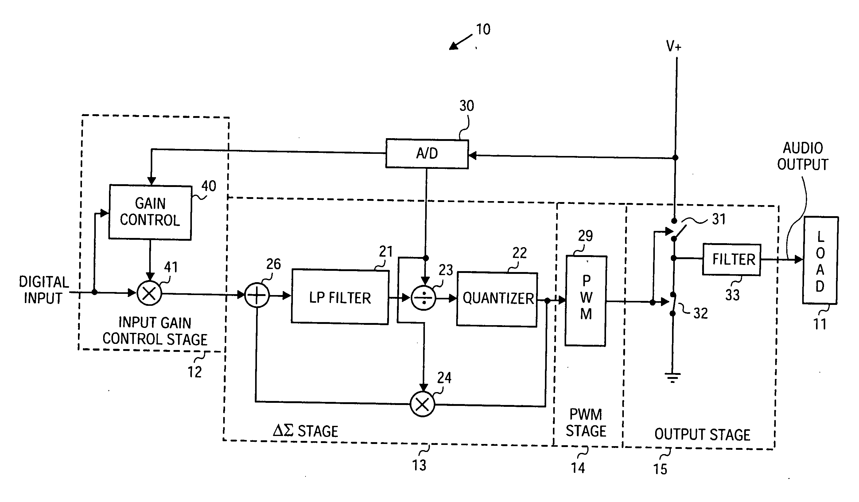
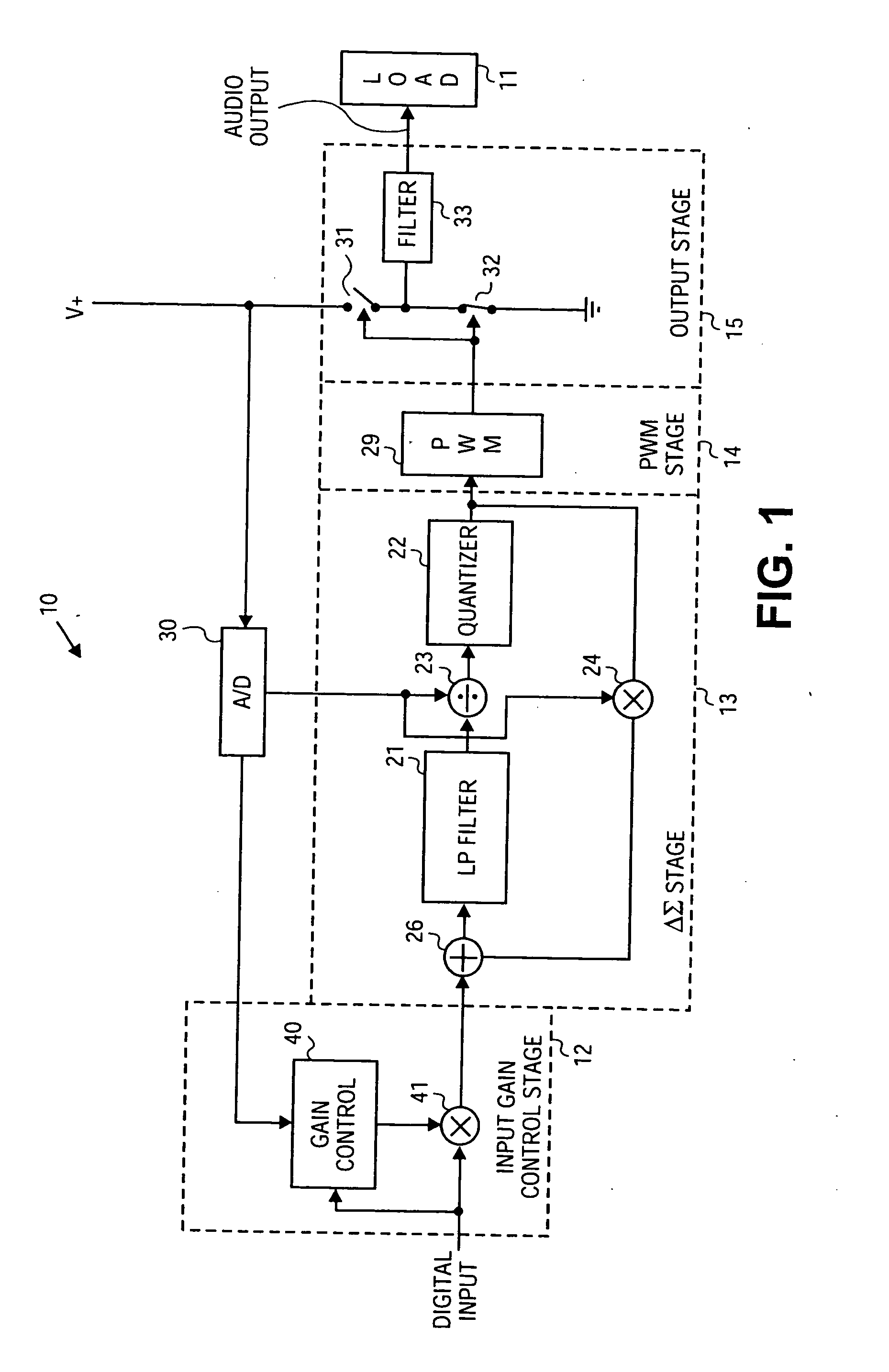
[0014] FIG. 1 illustrates an audio switching amplifier (also referred to as a switch mode amplifier) that implements a power supply based compression. The exemplary circuit of FIG. 1 is one embodiment for practicing the present invention. The embodiment of the invention shown in FIG. 1 is a switching amplifier circuit 10 having four stages to convert a digital input signal into an audio output. The audio output signal from switching amplifier circuit 10 is coupled to a load 11. Although only four stages are shown to describe the operation of the switching amplifier 10, other stages and / or circuitry may be present in other embodiments implementing the present invention.

[0015] In the exemplary embodiment of FIG. 1, an input gain control stage 12, delta-sigma (.DELTA..SIGMA.) stage 13, pulsewidth modulation (PWM) stage 14, and output stage 15 are the four stages of switching amplifier 10. Load 11 receives the audio output from output stage 15. The input to input gain control stage 12 i...


PUM


Abstract

A gain control at the input monitors an input signal and a supply voltage, which drives an output. The gain control adjusts the gain to compress the input signal when the supply voltage decreases in magnitude and / or the input signal is of such magnitude to cause the supply voltage to decrease.

Description

[0001] The present invention relates to a power supply based compression technique in a digital audio amplifier.BACKGROUND OF THE RELATED ART[0002] The use of switched mode output stage(s) in audio amplification, in which the conversion is performed digitally, allows audio output from digital signal input. The digital signal conversion may be achieved by a variety of devices. One particular technique utilizes a delta-sigma (.DELTA..SIGMA.) modulator, in which the digital input signal is filtered and then quantized to produce an output. In one switched technique, the noise-shaped quantized signal from the quantizer is coupled to a pulsewidth modulator (PWM), in which a value of the quantized signal controls the duty cycle of the PWM output. This PWM output then controls the operation of a switching device or devices, utilized as the output stage of an amplifier to drive a load. The filtered digital signal is used to modulate the pulsewidth of the PWM signal to control the duration of...

Claims


Application Information

Patent Timeline
Patent Type & Authority Applications(United States)
IPC IPC(8): H03M7/32H03F1/32H03F3/181H03F3/217H03G3/30H03G7/00
CPCH03F3/181H03F3/217H03F2200/03H03F2200/331H03F2200/351H03G3/3089H03G7/007
Inventor MELANSON, JOHN L.FEI, XIAOFANGABORIAU, JOHANN G.GREEN, STEVENRHODE, JASON P.
Owner CIRRUS LOGIC INC
Why Eureka
Try Eureka