Control system for architectural coverings with reversible drive and single operating element

Active Publication Date: 2004-11-18
HUNTER DOUGLAS INC
View PDF31 Cites 77 Cited by
  • Summary
  • Abstract
  • Description
  • Claims
  • Application Information

AI Technical Summary

Problems solved by technology

This can be especially confusing if the operating elements are tangled.
Inherent in the loop operating element system is the problem of having a very long operating element with which t

Method used


Image

  • Control system for architectural coverings with reversible drive and single operating element
  • Control system for architectural coverings with reversible drive and single operating element
  • Control system for architectural coverings with reversible drive and single operating element

Examples


first embodiment

[0171] Similar to the first embodiment, the various elements of the input assembly are supported by a right end cap 116'. As shown in FIGS. 9 and 10C, the clutch spring 448, the cord spool 190', the clock spring 186', the spring retainer 446, and the axle 188' are supported by a first end cap shaft 236', whereas the pulley 184' is rotatably supported on a second end cap shaft 238'. As discussed below, the control arm 444 is pivotally connected with the right end cap in another location.

[0172] As with the first embodiment, the axle 188' interfaces with the input assembly 174', the transmission 176', and the output assembly 178'. As such, additional descriptions of the various functions performed by the axle will be described below separately as part of the detailed descriptions of the input assembly, the transmission, and the output assembly.

[0173] As shown in FIG. 10A, the axle 188' of the second embodiment may include a plurality of outer surfaces defined along its length by varyin...

second embodiment

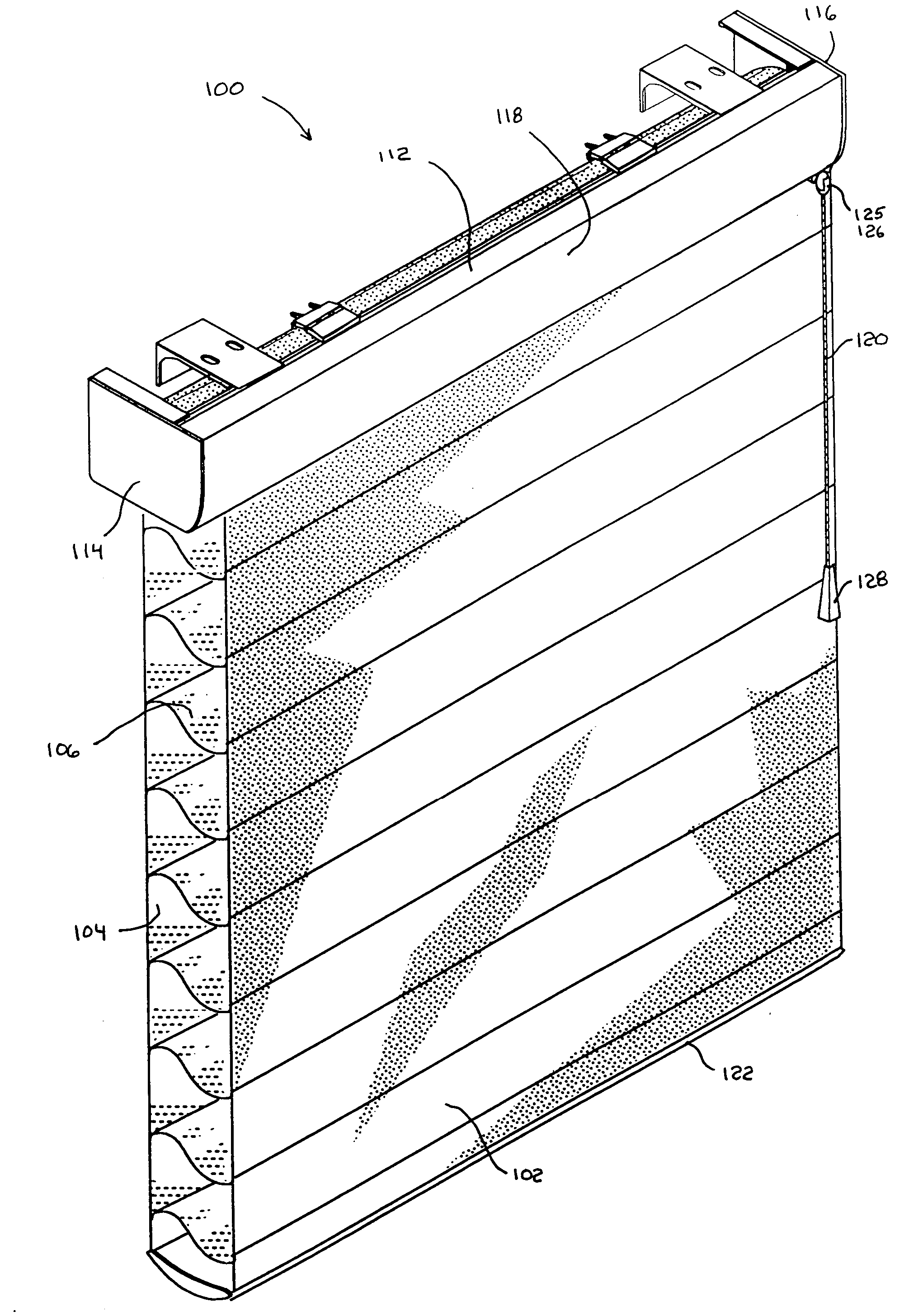
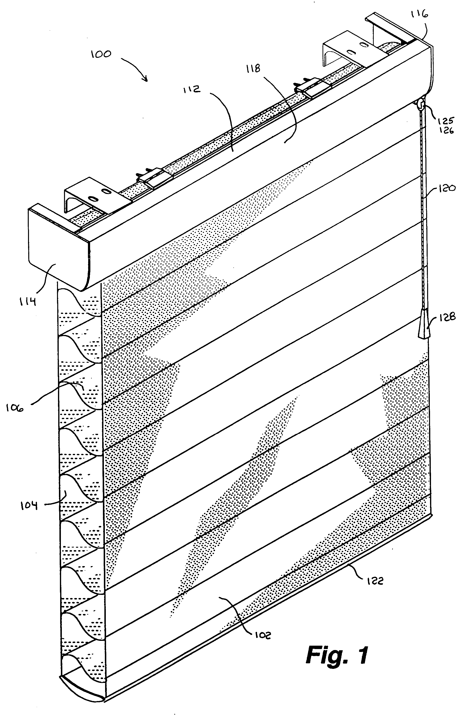
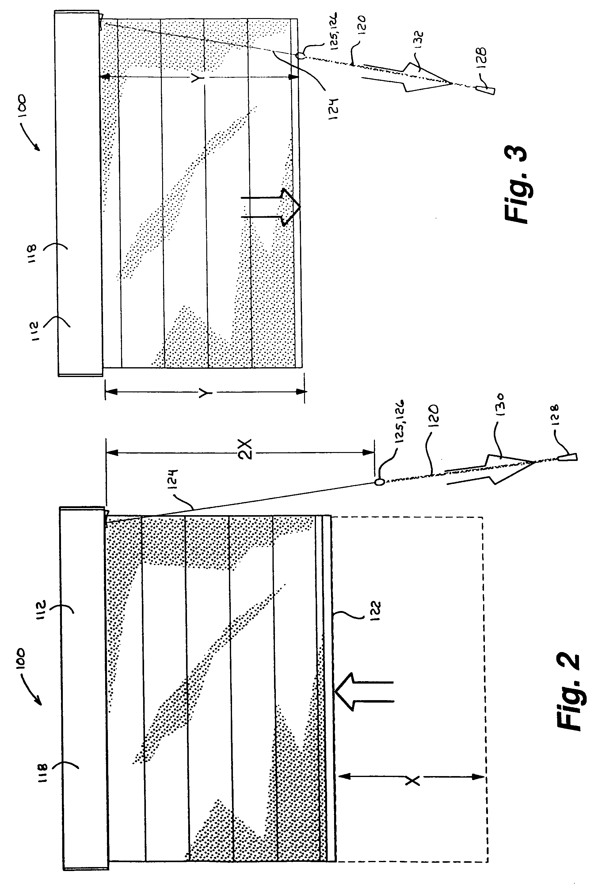
[0190] To summarize the operational description of the input assembly 174' on the second embodiment, as a user pulls on the pull cord 120 to move the covering 100 in the desired direction, the operating cord 124 is unwound from the cord spool 190', causing the cord spool to rotate in a counterclockwise direction. If the user pulls the pull cord in the upward operating direction 130 (see FIG. 2), the operating cord impinging on the channel 480 of the control arm 444 causes the control to pivot such that the hook 496 on the control arm engages the transmission 176', causing the head roller 108 to rotate in a direction to wrap the covering onto the head roller. Alternatively, if the user pulls the pull cord in the downward operating direction 132 (see FIG. 3), the control arm does not pivot to engage the hook with the transmission, causing the head roller to rotate in a direction to unwrap the covering from the head roller. Rotation of the cord spool 190' through the clutch spring 448 ...

third embodiment

[0216] Control System Overview

[0217] A third embodiment of the present invention is illustrated in FIGS. 16-21. The third embodiment of the control system 110" provides the same functionality as the first and second embodiments described above in that the control system allows a user to raise and lower the covering 100 by repeatedly pulling downwardly on the pull cord 120. Unlike the first and second embodiments, a user of the third embodiment cannot change the direction in which the head roller 108 rotates by altering the direction in which the pull cord 120 is pulled. Instead, the user of the third embodiment manually actuates a trigger 530 on a control arm 532 to change the direction in which the head roller 108 rotates. The operating cord of the third embodiment may also utilize the tassel 128 and stopper or coupler 125 described above. The third embodiment also provides for automatic retraction of the operating cord into the head rail assembly 112" along with the braking system...


PUM


Abstract

The present invention provides for retractable coverings for architectural openings utilizing a control system having a single operating element allowing a user to move a retractable covering between extended and retracted positions by imparting a repetitive motion to the operating element. The control system may include an input assembly, a transmission, and an output assembly cooperatively engaging to convert linear movement of the operating element into rotational movement of a head roller in the required direction to provide movement of the covering in the desired direction and distance. The input assembly may convert linear movement of the operating element into rotational movement imparted to the transmission. The input assembly may also engage the transmission to effect the direction of rotational output from the transmission. The transmission imparts rotational movement to the output assembly, which interfaces with the head roller to rotate the head roller and to provide a braking feature.

Description

[0001] This application claims priority to U.S. Provisional Application No. 60 / 452,222, filed Mar. 4, 2003, hereby incorporated by reference in its entirety as though fully set forth herein.[0002] a. Field of the Invention[0003] This invention relates to retractable coverings for architectural openings, and more particularly, an operating system for controlling retractable coverings for architectural openings using a single operating element.[0004] b. Background Art[0005] Operating systems utilized in window coverings for architectural openings, such as shade and blind assemblies are commonly used. Conventional shade and blind assemblies typically comprise a head rail, bottom rail, and slats or a covering disposed therebetween. Generally, a control system for raising and lowering such blinds or shades are installed in the head rail and may include an operating element, such as a cord, for lowering or raising the blinds or shades. The operating element is typically connected to pulle...

Claims


Application Information

Patent Timeline
IPC IPC(8): E06B9/262E06B9/322E06B9/34E06B9/42E06B9/68
CPCE06B9/262E06B9/322E06B9/34E06B9/42E06B9/68E06B2009/2627
Inventor SMITH, STEPHEN P.COLSON, WENDELL B.MILLER, JAMES L.
Owner HUNTER DOUGLAS INC
Why Eureka
Try Eureka