Vibrating type pressure sensor

a pressure sensor and vibration technology, applied in the direction of fluid pressure measurement, instruments, measurement devices, etc., can solve the problems of oscillatory pressure sensors, silicon has the property of being corroded by corrosive gases, and the diaphragm made of silicon substrates cannot be exposed directly to corrosive gases, etc., to avoid external electromagnetic noise, high precision, accurate results

Inactive Publication Date: 2004-11-25
FUJIKIN INC +1
View PDF1 Cites 7 Cited by
  • Summary
  • Abstract
  • Description
  • Claims
  • Application Information

AI Technical Summary

Benefits of technology

0016] According to the invention of claim 3, the pressure sensor is constructed such that the oscillatory force is applied from outside of the vacuum chamber, wiring for the oscillator being unnecessary so that externally induced electromagnetic noise is avoided. Further, there is provided an optical measuring means which comprises a light transmitting part at a desired position, wherein a light beam is allowed to pass through the light transmitting part to enter the vacuum chamber for incidence upon the oscillatory plate, the light beam reflected by the resonating oscillatory plate being allowed to exit through the light transmitting part, wherein the resonant frequency of the oscillator is measured by detecting the reflected light beam. The measurement of the resonant frequency is effected by non-contact optical means, thereby making it possible to measure the resonant frequency with great precision.
0017] According to the invention of claim 4, the optical measuring means comprises an optical fibre for the incident light beam, an incidence lens for focussing the incident light beam on the surface of the oscillator, a reflection lens for converging the beam reflected by the oscillator, and an optical fibre for guiding the reflected beam, whereby both the incident light beam and the reflected beam are guided as desired. Further, since the beam is focussed on the oscillator by means of the incidence lens, the resonance of the oscillator is accurately converted into a directional oscillation (fluctuation) of the reflected beam. As a result, changes in intensity of the reflected beam incident upon the optical fibre for reflection are accurately obtained.
0018] According to the invention of claim 5, the optical measuring means comprises a laser-Doppler vibration meter that is adapted to receive the beam reflected by the oscillator. The resonance speed of the oscillator is therefore accurately detected by the laser-Doppler method, thereby accurately obtaining the resonance frequency from changes in the oscillation speed.
0019] According to the invention of claim 6, the optical measuring means comprises a half-split light receiving element for receiving the reflected beam, thereby making it possible to convert the directional oscillation of the reflected beam into an oscillation of a differential output of the half-split light receiving element, such that the resonant frequency can be easily and accurately determined by subjecting the oscillation of the differential output to high-speed Fourier transformation or the like.
0020] According to the invention of claim 7, the pressure detector is constructed such that a piezo-electric actuator is attached to an outside surface of the pressure-sensing diaphragm, the wall body, or the light transmitting part, wherein oscillation of the piezo-electric actuator subjects the oscillator of the pressure-sensing diaphragm to a forced oscillation. As a result, circuit wiring can be eliminated from the pressure-sensing diaphragm and the oscillator, thereby avoiding electric noise.
0021] According to the invention of claim 8, an alternating current voltage is applied between an electrode arranged outside of the light transmitting part and the stainless steel pressure-sensing diaphragm, wherein said alternating current voltage is adapted to change the inductive charge that is induced electrostatically on the diaphragm and the electrode, thereby subjecting the diaphragm to a forced oscillation with the force of the static electricity. As a result, circuit wiring can be eliminated from the diaphragm and oscillator for accurately measuring the resonant frequency with electrical noise being excluded.

Problems solved by technology

The oscillatory pressure sensor has a serious disadvantage in that silicon has the property that it is corroded by corrosive gases.
A diaphragm made of a silicon substrate cannot therefore be exposed directly to corrosive gases.
However, detecting the gas pressure indirectly has a disadvantage in that the pressure is dispersed and dissipated when the gas pressure is converted to oil pressure, thus greatly reducing the sensitivity and accuracy of the sensor.
Furthermore, since silicon oil is used, there is a high risk of the oil being ignited when a high temperature gas is detected.
This means that the method has some practical limitations with regard to heat resistance.

Method used


Image

  • Vibrating type pressure sensor
  • Vibrating type pressure sensor
  • Vibrating type pressure sensor

Examples


Embodiment Construction

[0089] The following embodiments of an oscillatory pressure sensor are described in detail with reference to the attached drawings hereunder.

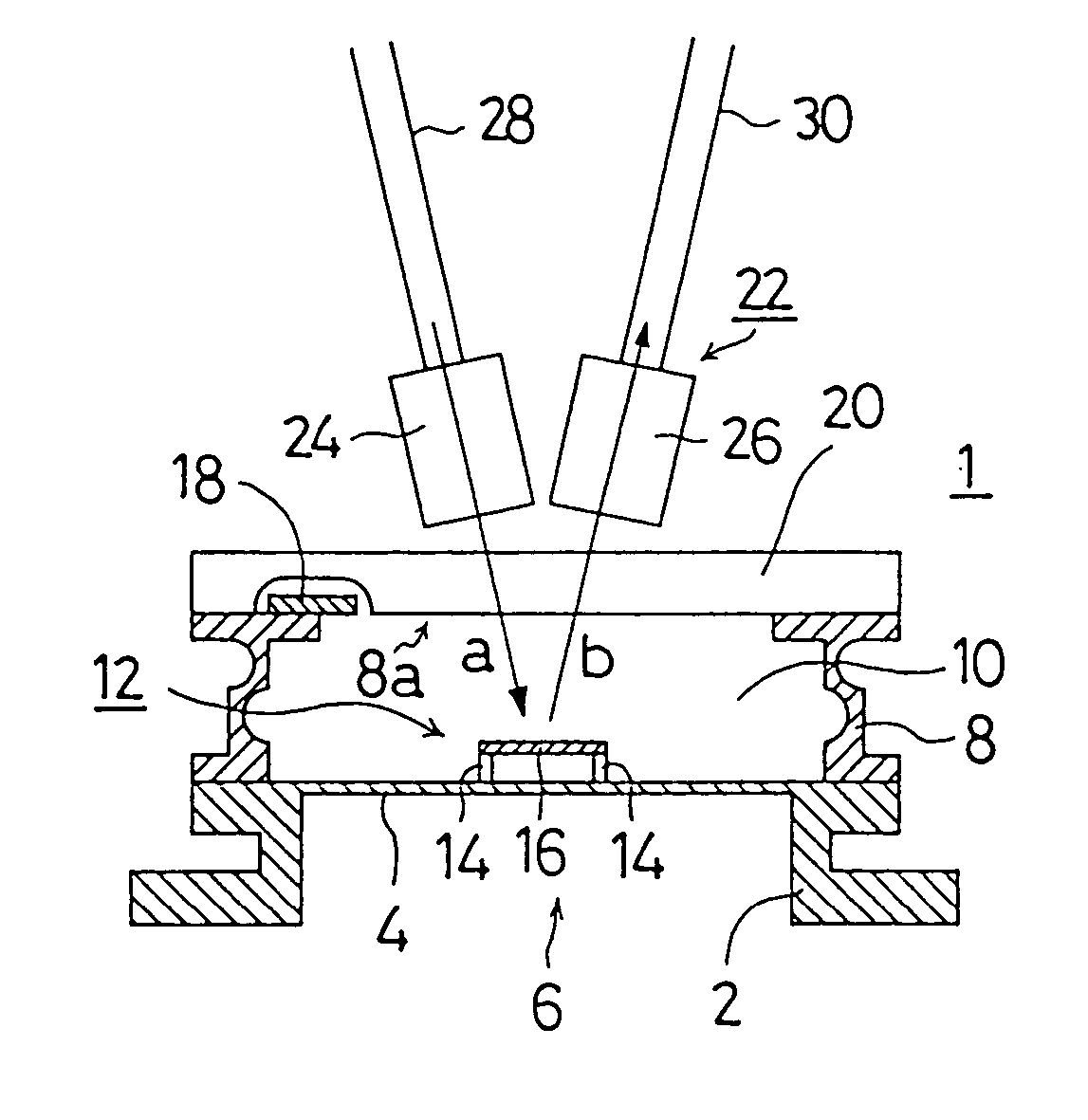
[0090] FIG. 1 is a longitudinal sectional view of an oscillatory pressure sensor illustrating an embodiment of the present invention. The oscillatory pressure sensor 1 comprises an ring-shaped frame body 2 having a pressure sensing space 6 therein that is adapted to receive an inflowing fluid such a gas, a pressure-sensing diaphragm 4 formed on an upper surface of the frame body 2 such that the pressure of the fluid is directly applied to the diaphragm 4, a further ring-shaped wall body 8 installed on an upper surface of diaphragm 4, and a light transmitting part 20 that closes an upper opening of the wall body 8 in an air-tight manner.

[0091] The frame body 2 and the pressure-sensing diaphragm 4 are made of a highly corrosion-resistant stainless-steel, such, for example, as SUS316L having regard to the instances in which they come into contact ...


PUM

PropertyMeasurementUnit
thickaaaaaaaaaa
current valueaaaaaaaaaa
temperatureaaaaaaaaaa

Abstract

A high-sensitive and high accuracy vibrating type pressure sensor (1) allowing a corrosive gas pressure to be directly applied thereto, having a heat resistance, and having no room for mixing of noise into a vibrator, comprising a stainless steel pressure receiving diaphragm (4) for receiving a fluid pressure P on a rear surface side, the vibrator (12) formed on the front surface side of the pressure receiving diaphragm (4), a wall body (8) disposed so as to surround the periphery of the vibrator (12), and a permeable part (20) for light transmission for changing an internal space in which the vibrator (12) is present into a vacuum chamber (10) by closing an opening part (8a) in the wall body (8), whereby, since the diaphragm (4) is formed of the stainless steel with corrosion resistance, the sensor can also be applied to corrosive fluid, since circuit wiring is eliminated from the vibrator (12) and the vibrator is isolatedly disposed in the vacuum chamber (10), mixing of electromagnetic noise can be eliminated, and since the resonance frequency fn of the vibrator (12) is performed by optical measurement in the state of non-contact, extremely high-sensitive and high-accuracy detection can be performed. A forced vibration device (57) can also be operated by piezo driving and electrostatic driving from the outside without generating noise.

Description

[0001] The present invention relates principally to an oscillatory pressure sensor for use in semiconductor manufacturing facilities or chemical plants and the like, and relates more particularly to an oscillatory pressure sensor that generates no electrical noise, has high sensitivity and accuracy, and is heat resistant and suitable for use with corrosive fluids.BACKGROUND TO THE INVENTION[0002] It is common practice in semiconductor manufacturing facilities and chemical plants to supply a plurality of gaseous raw materials at prescribed flow rates for chemical reaction in a reaction furnace to produce high purity target gases or reactants. The pressure of the gaseous raw materials is detected and regulated, and the gas flow rate is controlled automatically at a predetermined value. The gas pressure needs to be detected with great accuracy in order to regulate the gas flow rate with high precision.[0003] A pressure transducer is normally employed to measure gas pressure, but where ...

Claims


Application Information

Patent Timeline
Patent Type & Authority Applications(United States)
IPC IPC(8): G01L9/00
CPCG01L9/0017
Inventor ESASHI, MASAYOSHIHIRATA, KAORU
Owner FUJIKIN INC
Why Eureka
Try Eureka