
Liquid droplet ejecting apparatus, liquid droplet ejecting system, electro-optical device, method of manufacturing electro-optical device, method of forming a metal wiring line, and electronic apparatus

a technology of liquid droplet ejection and liquid droplet, which is applied in the direction of non-linear optics, instruments, coatings, etc., can solve the problems of difficult to stably form (draw) a pattern with high accuracy and disturbed atmosphere in the chamber

Inactive Publication Date: 2004-11-25
SEIKO EPSON CORP
View PDF15 Cites 27 Cited by
  • Summary
  • Abstract
  • Description
  • Claims
  • Application Information

AI Technical Summary

Benefits of technology

[0011] Therefore, it is an object of the present invention to provide a liquid droplet ejecting apparatus and a liquid droplet ejecting system capable of forming (drawing) a pattern from ejected liquid droplets with high accuracy and enhancing throughput (production efficiency), an electro-optical device manufactured by using the liquid droplet ejecting apparatus, a method of manufacturing an electro-optical device by using the liquid droplet ejecting apparatus, a method of forming a metal wiring line by using the liquid droplet ejecting apparatus, and an electronic apparatus comprising the electro-optical device.

Problems solved by technology

However, in the conventional liquid droplet ejecting apparatus, since a work is heated when drying the liquid droplets ejected to the work, the atmosphere (environment) in the chamber is disturbed.
Specifically, the environmental temperature is raised and the work is thermally expanded, so that it is difficult to stably form (draw) a pattern with high accuracy.

Method used


Image

  • Liquid droplet ejecting apparatus, liquid droplet ejecting system, electro-optical device, method of manufacturing electro-optical device, method of forming a metal wiring line, and electronic apparatus
  • Liquid droplet ejecting apparatus, liquid droplet ejecting system, electro-optical device, method of manufacturing electro-optical device, method of forming a metal wiring line, and electronic apparatus
  • Liquid droplet ejecting apparatus, liquid droplet ejecting system, electro-optical device, method of manufacturing electro-optical device, method of forming a metal wiring line, and electronic apparatus

Examples


Embodiment Construction

[0074] Now, a liquid droplet ejecting apparatus and a liquid droplet ejecting system according to the present invention will be described in detail in conjunction with preferred embodiments shown in the accompanying drawings.

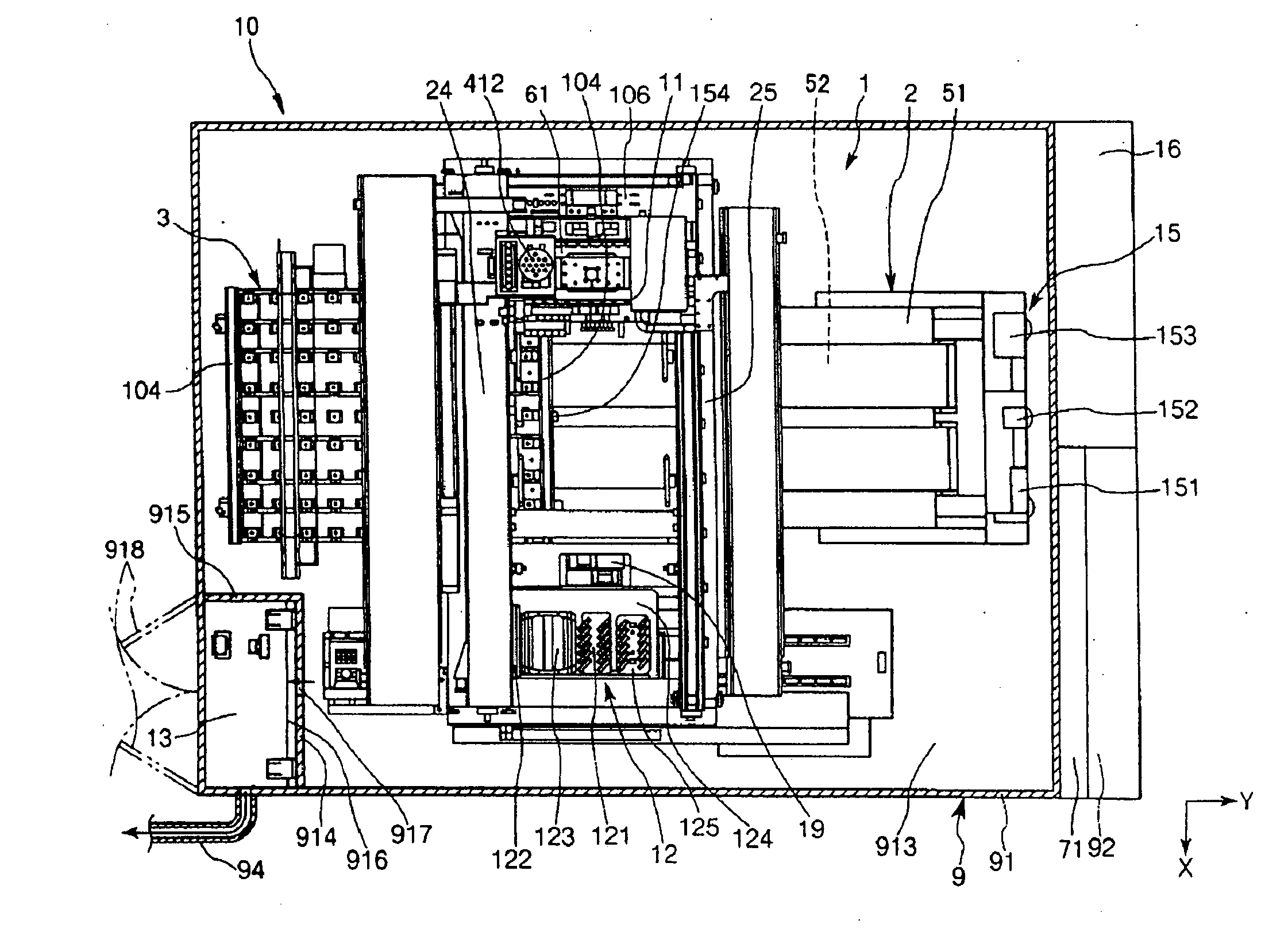
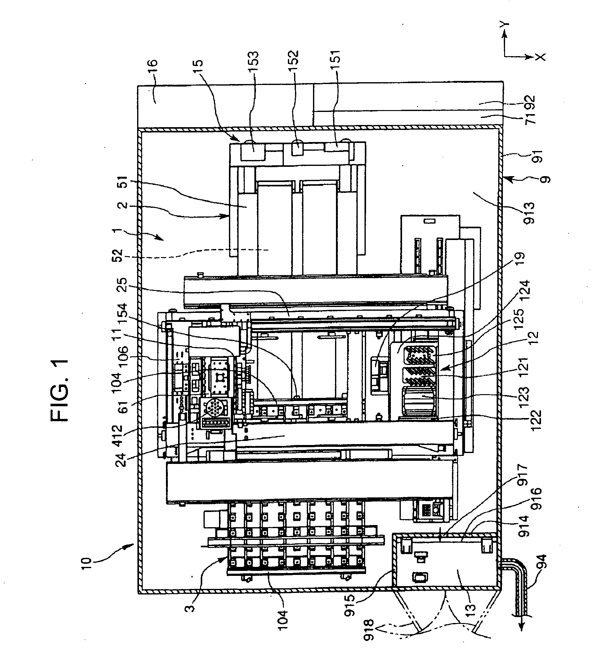
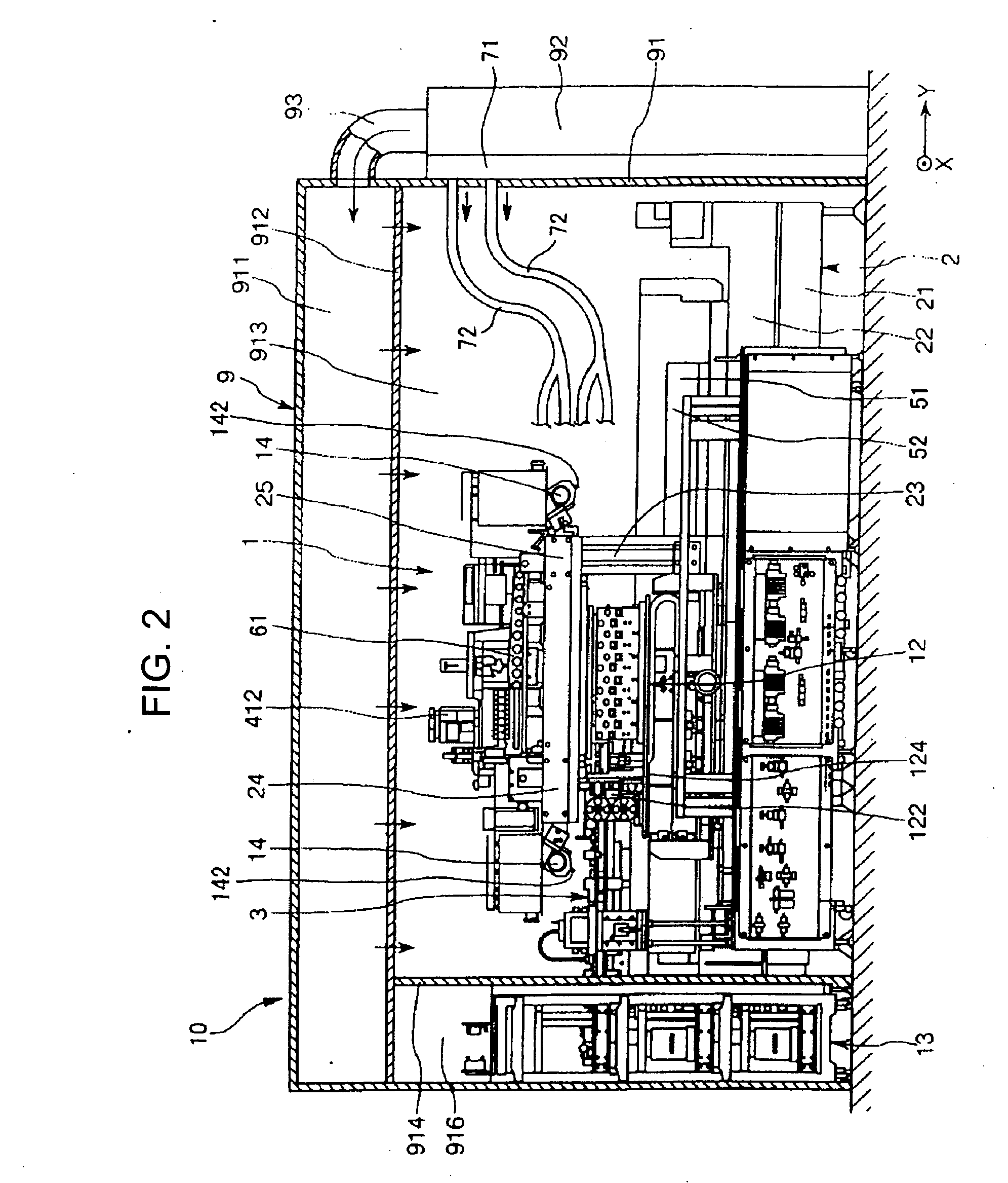
[0075] FIGS. 1 and 2 are a plan view and a side view illustrating an embodiment of a liquid droplet ejecting apparatus and a liquid droplet ejecting system according to the present invention, respectively. Hereinafter, for the purpose of convenient explanation, one horizontal direction (the direction corresponding to the right-left direction in FIGS. 1 and 2) is referred to as the "Y-axis direction", and another horizontal direction (the direction corresponding to the up-down direction in FIG. 1) perpendicular to the Y-axis direction is referred to as the "X-axis direction". Further, in the Y-axis direction, movement to right in FIGS. 1 and 2 is referred to as "Y-axis advance", and movement to left in FIGS. 1 and 2 is referred to as "Y-axis retreat". Furthermore...


PUM


Abstract

[Object] To provide a liquid droplet ejecting apparatus capable of forming (drawing) a pattern from ejected liquid droplets with high accuracy and enhancing throughput (production efficiency), a liquid droplet ejecting system, an electro-optical device, a method of manufacturing an electro-optical device, a method of forming a metal wiring line, and an electronic apparatus. [Solving Means] A liquid droplet ejecting apparatus 1 according to the present invention comprises: a main body 2, a work carrying table for supporting a work, an Y-directional movement mechanism for moving the work carrying table in the horizontal direction (hereinafter, referred to as an "Y-axis direction") relative to the main body 2, a droplet ejecting head for ejecting liquid droplets to the work supported by the work carrying table, and at least one blowing unit 14 for blowing a gas towards the work supported by the work carrying table to dry the liquid droplets ejected to the work, wherein the gas has a condition almost equal to the atmosphere in which the liquid droplet ejecting apparatus 1 is placed.

Description

[0001] 1. Technical Field of the Invention[0002] The present invention relates to a liquid droplet ejecting apparatus, a liquid droplet ejecting system, an electro-optical device, a method of manufacturing an electro-optical device, a method of forming a metal wiring line, and an electronic apparatus.[0003] 2. Description of the Related Art[0004] There have been suggested industrial liquid droplet ejecting apparatuses (ink-jet drawing apparatuses) used for manufacturing, for example, color filters of liquid crystal display devices or organic EL (electroluminescence) devices, or for forming metal wiring lines on substrates, by adapting an ink-jet method (a liquid droplet ejecting method) of ink-jet printers (for example, see Patent Document 1).[0005] The liquid droplet ejecting apparatus forms (draws) a predetermined pattern on a work by ejecting liquid droplets while relatively moving a work carrying table mounted with a work such as a substrate and a droplet ejecting head. In the c...

Claims


Application Information

Patent Timeline
IPC IPC(8): B05C5/00B05C9/12G02B5/20B41J2/01G02F1/13H01L21/288H01L51/50H05B33/10
CPCB41J2/01
Inventor KOJIMA, KENJIYODA, TATSUO
Owner SEIKO EPSON CORP
Learn More