Diffractive optical element that polarizes light and an optical pickup using the same

a technology of diffracted light and optical elements, applied in the direction of polarising elements, instruments, light beam reproducing, etc., can solve the problems of diffracted light trapped in the substrate, limiting the potential of optical elements on such substrates, and diffraction of light trapped within the substra

Inactive Publication Date: 2004-11-25
PANASONIC CORP
View PDF10 Cites 101 Cited by
  • Summary
  • Abstract
  • Description
  • Claims
  • Application Information

AI Technical Summary

Problems solved by technology

This gives rise to the problem of the diffracted light being trapped within the substrate 201.
However, when a diffractive optical element pattern is formed in this way, there is still the problem of the diffracted light being trapped in the substrate when the pattern pitch .LAMBDA. of the diffractive optical element pattern is smaller than the wavelength .lambda. of the incident light.
The above problem means that even if a diffractive optical element pattern is capable of polarizing light, the diffracted beams produced by the diffractive optical element pattern will not exit the substrate.
This greatly limits the potential of such substrates as optical elements.
A prism-shaped PBS is a relatively large component, and so makes miniaturization of the optical pickup difficult.

Method used


Image

  • Diffractive optical element that polarizes light and an optical pickup using the same
  • Diffractive optical element that polarizes light and an optical pickup using the same
  • Diffractive optical element that polarizes light and an optical pickup using the same

Examples


first embodiment

[0062] First Embodiment

[0063] FIG. 5 is a perspective drawing showing the external appearance of a transmittive-polarization type diffractive optical element 100 to which the first embodiment of the present invention relates.

[0064] As shown in FIG. 5, the diffractive optical element 100 is composed of a substrate 1 that is made of a transparent substance such as glass and has a first diffractive optical element pattern 4 on a main surface 2 and second diffractive optical element patterns 5 and 6 formed on an opposite main surface 3.

[0065] The first diffractive optical element pattern 4 and second diffractive optical element patterns 5 and 6 are each composed of slits. The slits in the first diffractive optical element pattern 4 are formed with a rectangular cross-section and a pattern pitch that is no greater than the wavelength .lambda. of the incident light. This kind of pattern can be formed by dry etching, such as by performing reactive ion-beam etching (RIBE) in the presence of...

second embodiment

[0085] Second Embodiment

[0086] FIG. 8 shows the construction of the diffractive optical element 110 of the second embodiment of the present invention. Unlike the diffractive optical element 100 of the first embodiment, this diffractive optical element 110 has the first diffractive optical element pattern 4 and the second diffractive optical element patterns 5 and 6 formed on the same main surface (main surface 2) of the substrate 1. Many construction elements are the same as those in the first embodiment, so that these have been given the same reference numerals as before and their explanation has been omitted.

[0087] As shown in FIG. 8, the diffractive optical element 110 is composed of a substrate 1 that has a polarizing first diffractive optical element pattern 4 on a main surface 2 and light-projecting second diffractive optical element patterns 5 and 6 positioned on the same main surface 2 so as to be incident to diffracted light that is produced by the first diffractive optical...

third embodiment

[0096] Third Embodiment

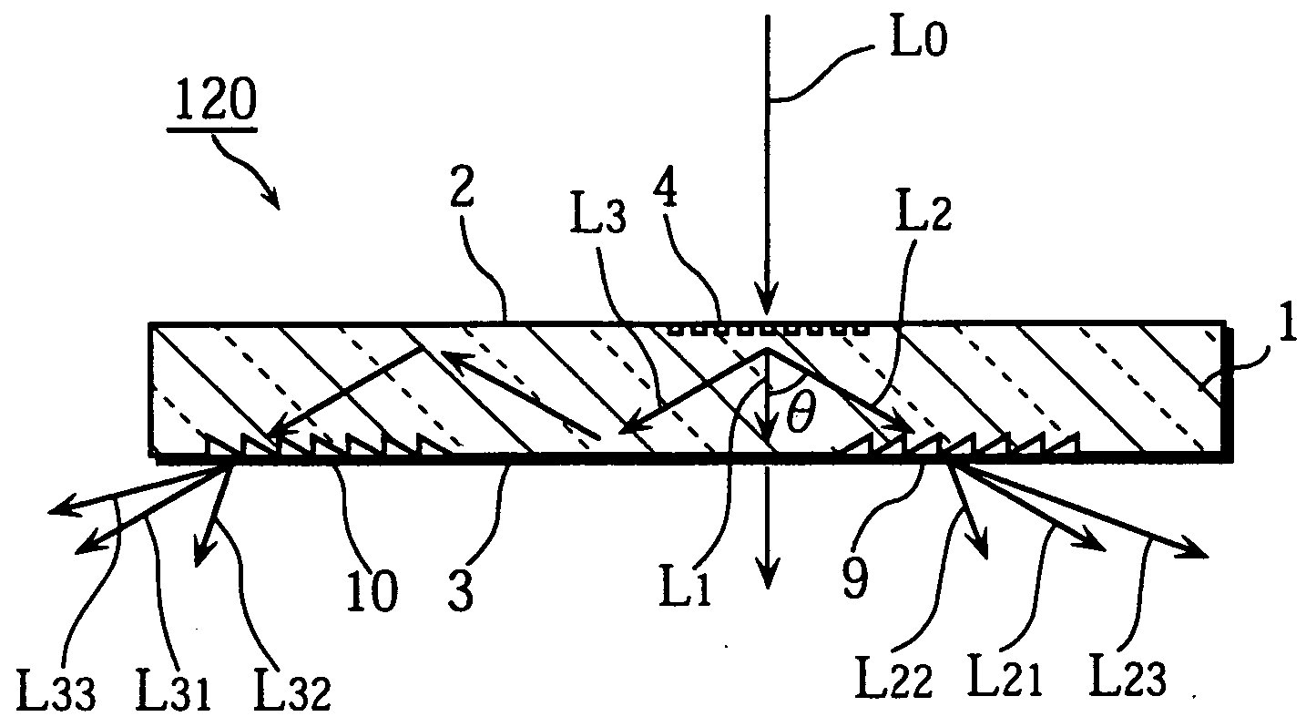
[0097] FIG. 10 shows the construction of a diffractive optical element 120 of the third embodiment of the present invention.

[0098] As shown in FIG. 10, the diffractive optical element 120 is composed of a substrate 1 that has a polarizing first diffractive optical element pattern 4 on a main surface 2 and light-projecting second diffractive optical element patterns 9 and 10 on an opposite main surface 3. These second diffractive optical element patterns 9 and 10 are positioned so as to be either directly incident to diffracted light that is produced by the first diffractive optical element pattern 4 or incident to the diffracted light after it has been subjected to total internal reflection by the main surfaces two times. These second diffractive optical element patterns 9 and 10 are made up of slits that are triangular in cross-section and so will hereafter be referred to as "sawtooth patterns".

[0099] FIG. 11 is an enlargement of one of the slits that compose...


PUM

PropertyMeasurementUnit
angleaaaaaaaaaa
diffraction angleaaaaaaaaaa
refractive indexaaaaaaaaaa

Abstract

A first diffractive optical element pattern with a pattern pitch that is no greater than a wavelength of incident light is formed on a first main surface of substrate such as a glass plate. Second diffractive optical element patterns are formed at positions that are respectively incident to positive first-order diffracted light and negative first-order diffracted light produced by the first diffractive optical element pattern. Negative first-order diffracted light produced by each second diffractive optical element pattern is incident upon a boundary face of the substrate at an angle that is smaller than the critical angle, and so exits the substrate.

Description

[0001] (1) Field of the Invention[0002] The present invention relates to a diffractive optical element that can be used in a variety of applications, such as in optical information processing equipment and optical communication equipment. In particular, the invention relates to a diffractive optical element that polarizes light.[0003] (2) Related Art[0004] FIG. 1 is a cross-sectional drawing showing the construction of a conventional diffractive optical element 200.[0005] The arrows in FIG. 1 show the courses taken by light rays. This is also the case in the following drawings.[0006] As shown in FIG. 1, the diffractive optical element 200 is composed of a substrate 201 that is made of transparent plate glass and has a diffractive optical element pattern 203 formed on a main surface 202.[0007] The incident light L.sub.0 is monochromatic and has the wavelength .lambda.. When this light strikes the diffractive optical element pattern 203 on the main surface 202 at an angle of 90.degree...

Claims


Application Information

Patent Timeline
Patent Type & Authority Applications(United States)
IPC IPC(8): G02B5/18G02B5/30G11B7/12G11B7/135G11B11/105
CPCG02B5/1809G02B5/1819G02B5/3025G02B27/4238G02B27/4277G11B7/123G11B7/1353G11B7/1395G11B11/10543
Inventor NAKANISHI, HIDEYUKITAKASUKA, SHOICHIIJIMA, SHINICHIYOSHIKAWA, AKIOSHIONO, TERUHIRO
Owner PANASONIC CORP
Why Eureka
Try Eureka