Method and installation for the densification of substrates by means of chemical bapour infiltration

a technology of densification and chemical vapor, which is applied in the direction of friction lining, mechanical equipment, coatings, etc., can solve the problems of reducing the space available into which substrates can be loaded, reducing the degree of densification, and reducing the efficiency of densification process, so as to reduce the loading capacity, and improve the effect of distribution and preheating of reagent gas

Inactive Publication Date: 2004-12-02
MESSIER BUGATTI INC
View PDF6 Cites 29 Cited by
  • Summary
  • Abstract
  • Description
  • Claims
  • Application Information

AI Technical Summary

Benefits of technology

[0009] An object of the invention is to provide a method enabling the distribution and the preheating of the reagent gas to be improved, and more generally enabling densification gradients between substrates situated at different locations in the loading zone to be reduced, and to achieve this without decreasing loading capacity, and possibly even while increasing it.
[0014] In order to enhance preheating, the reagent gas advantageously flows inside the duct while making contact with walls forming heat exchanger surfaces that extend into the inside of the duct.

Problems solved by technology

A densification gradient is observed between the substrates situated at the bottoms of the stacks and the other substrates, which gradient becomes greater the more insufficient the preheating of the reagent gas.
However, for a given total enclosure volume, that would reduce the space available into which substrates can be loaded.
Unfortunately, the processes of densification by chemical vapor infiltration are lengthy and expensive to implement, so installations need to have their loading capacities used to the full.

Method used


Image

  • Method and installation for the densification of substrates by means of chemical bapour infiltration
  • Method and installation for the densification of substrates by means of chemical bapour infiltration
  • Method and installation for the densification of substrates by means of chemical bapour infiltration

Examples


Embodiment Construction

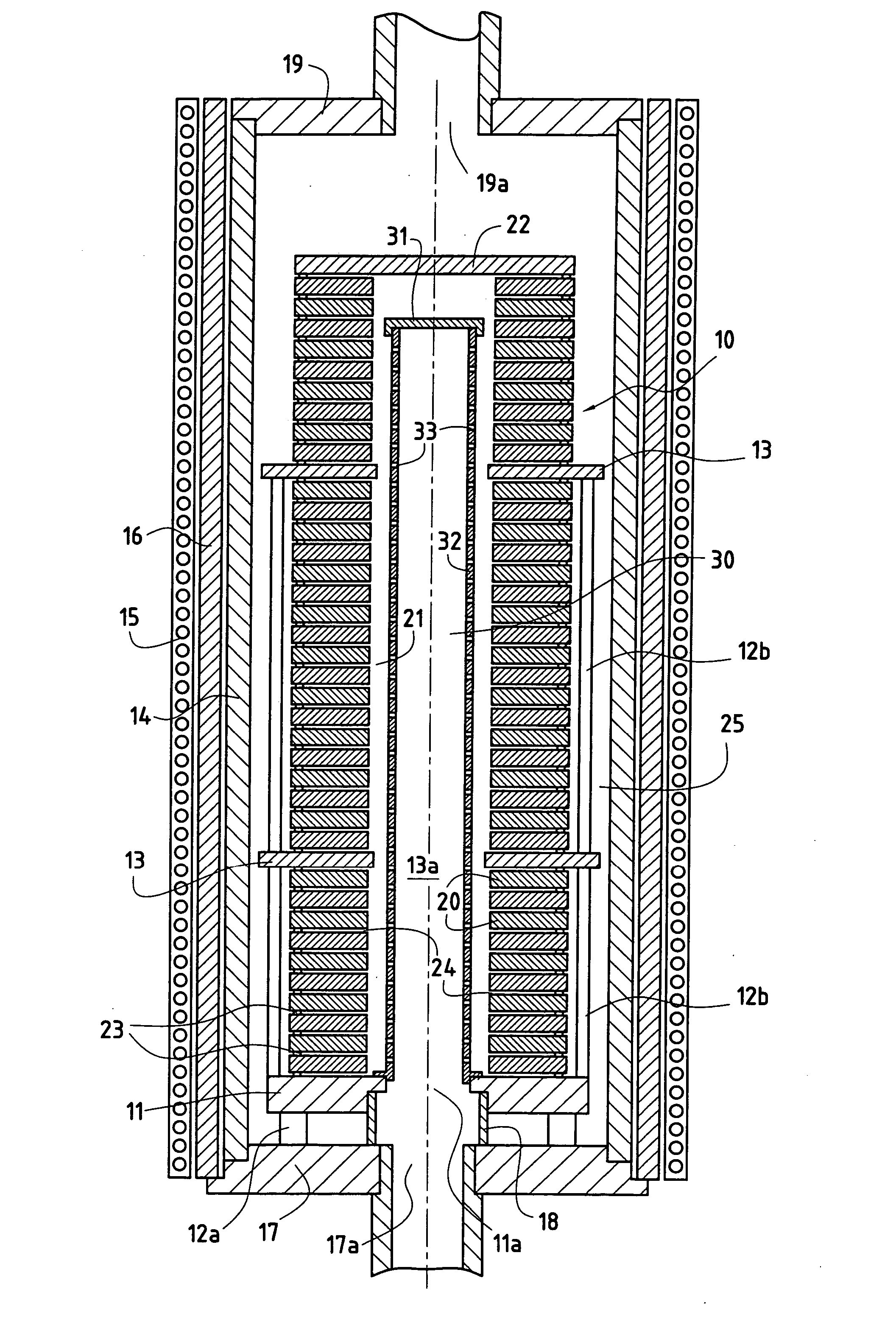
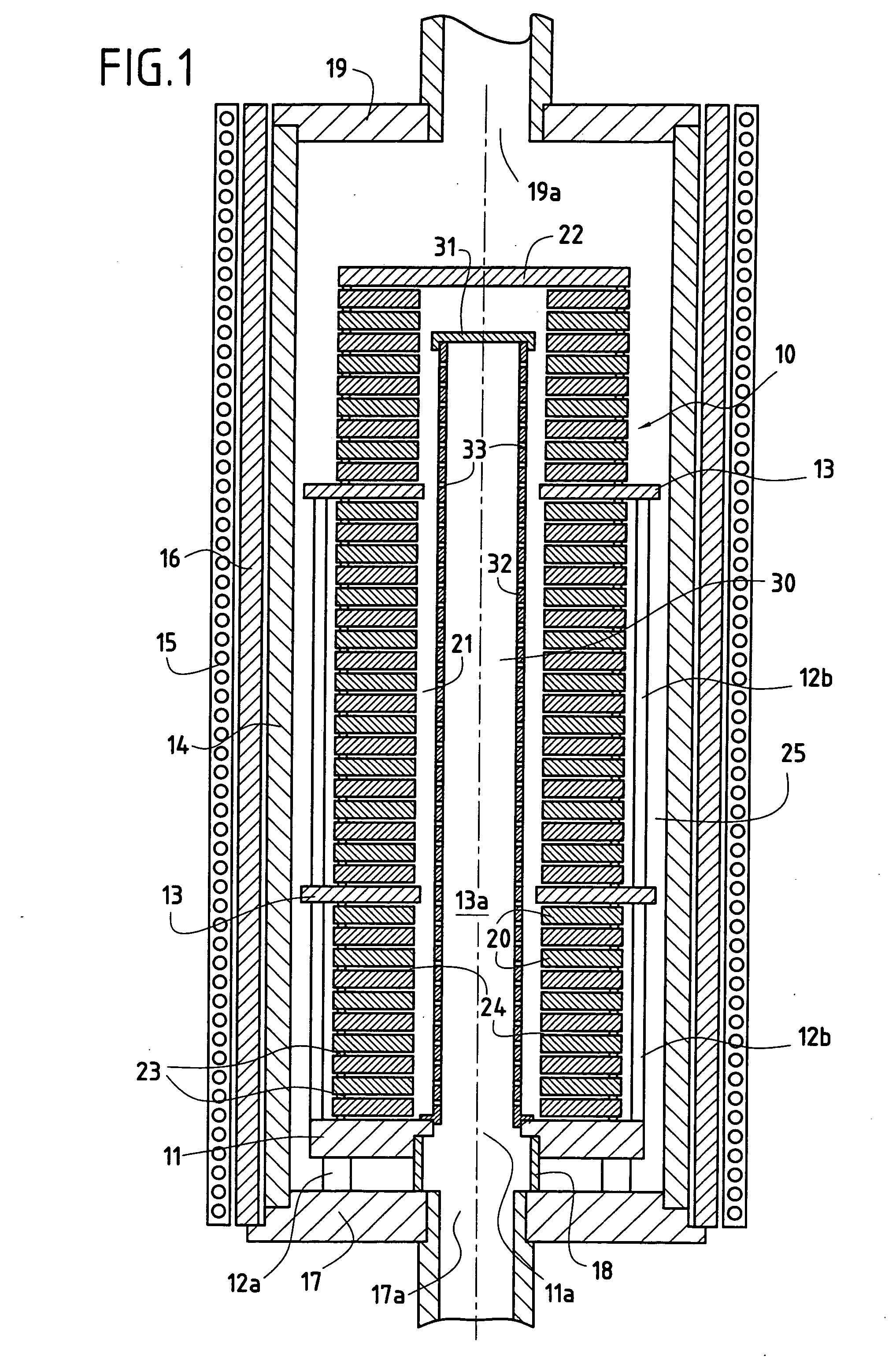
[0031] FIG. 1 is a diagram of an enclosure 10 containing a load of porous substrates 20. By way of example, the substrates 20 are carbon fiber preforms or blanks constituted by pre-densified preforms, which preforms or blanks are for use in making brake disks of carbon / carbon (C / C) composite material by being densified with a matrix of pyrolytic carbon.

[0032] The load is in the form of a stack of substrates defining an inside volume 21 formed by the central passages in the vertically-aligned substrates. The stack is carried by a bottom support plate 11 standing on legs 12a. It may be made up of a plurality of superposed sections that are separated from one another by one or more intermediate support plates 13. The plate 11 is provided with an opening 11a which is in axial alignment with the central passages through the substrates 20 and with openings 13a in the intermediate plates 13. At its top, the stack of substrates is provided with a cover 22 closing the internal volume 21. The...


PUM

PropertyMeasurementUnit
temperatureaaaaaaaaaa
lengthaaaaaaaaaa

Abstract

A method of densifying porous substrates by chemical vapor infiltration comprises loading porous substrates for densification in a loading zone of an enclosure (10), heating the internal volume of the enclosure, and introducing a reagent gas into the enclosure though an inlet situated at one end of the enclosure. Before coming into contact with substrates (20) situated in the loading zone, the reagent gas admitted into the enclosure is preheated, at least in part, by passing along a duct (30) connected to the gas inlet and extending through the loading zone, the duct being raised to the temperature inside the enclosure, and the preheated reagent gas is distributed in the loading zone through one or more openings (33) formed in the side wall (32) of the duct, along the duct.

Description

[0001] The invention relates to chemical vapor infiltration techniques. The field of application of the invention is densifying porous substrates, in particular making composite material parts by densifying fiber substrates by means of a matrix.[0002] In conventional manner, a method of densifying substrates by chemical vapor infiltration comprises the steps of loading porous substrates to be densified into a loading zone of an enclosure, heating the internal volume of the enclosure, introducing a reagent gas in the enclosure through an inlet situated at one end thereof, and preheating the reagent gas after it has entered into the enclosure and before it comes into contact with the parts situated in the loading zone.[0003] The temperature and the pressure that exist inside the enclosure are selected so as to enable the reagent gas to diffuse into the pores of the substrates and deposit therein the material for constituting the matrix, either by one or more components of the reagent ...

Claims


Application Information

Patent Timeline
Patent Type & Authority Applications(United States)
IPC IPC(8): C04B35/83F16D69/00C04B41/85C23C16/04C23C16/44C23C16/455
CPCC04B35/83C23C16/045C23C16/455C23C16/45578Y10S427/10C23C16/04C04B41/45
Inventor BERNARD, BRUNOGOUJARD, STEPHANEBERTRAND, SEBASTIEN
Owner MESSIER BUGATTI INC
Why Eureka
Try Eureka