Cleaning equipment and use thereof

a technology of cleaning equipment and cleaning medium, which is applied in the direction of electrostatic cleaning, hollow article cleaning, tank cleaning, etc., can solve the problems of limited amount of cleaning medium, frequent problem of cleaning medium with suspended material, etc., and achieve the effect of less expensiv

Inactive Publication Date: 2004-12-02
ALFA LAVAL TANK EQUIP
View PDF12 Cites 47 Cited by
  • Summary
  • Abstract
  • Description
  • Claims
  • Application Information

AI Technical Summary

Benefits of technology

0008] When, as stated in claim 2, the equipment is constructed such that it may be mounted in one and the same hole in the tank, the installation is very compact, and the mounting is therefore simpler and less expensive.

Problems solved by technology

This cleaning medium with suspended material is frequently a problem, since it must be stored for subsequent cleaning in order to avoid pollution.
This is a drawback where limited amounts of cleaning medium are available, such as on drilling platforms and similar locations, just as it requires a sufficient tank capacity for the storage of the cleaning medium pumped out.

Method used


Image

  • Cleaning equipment and use thereof
  • Cleaning equipment and use thereof

Examples


Embodiment Construction

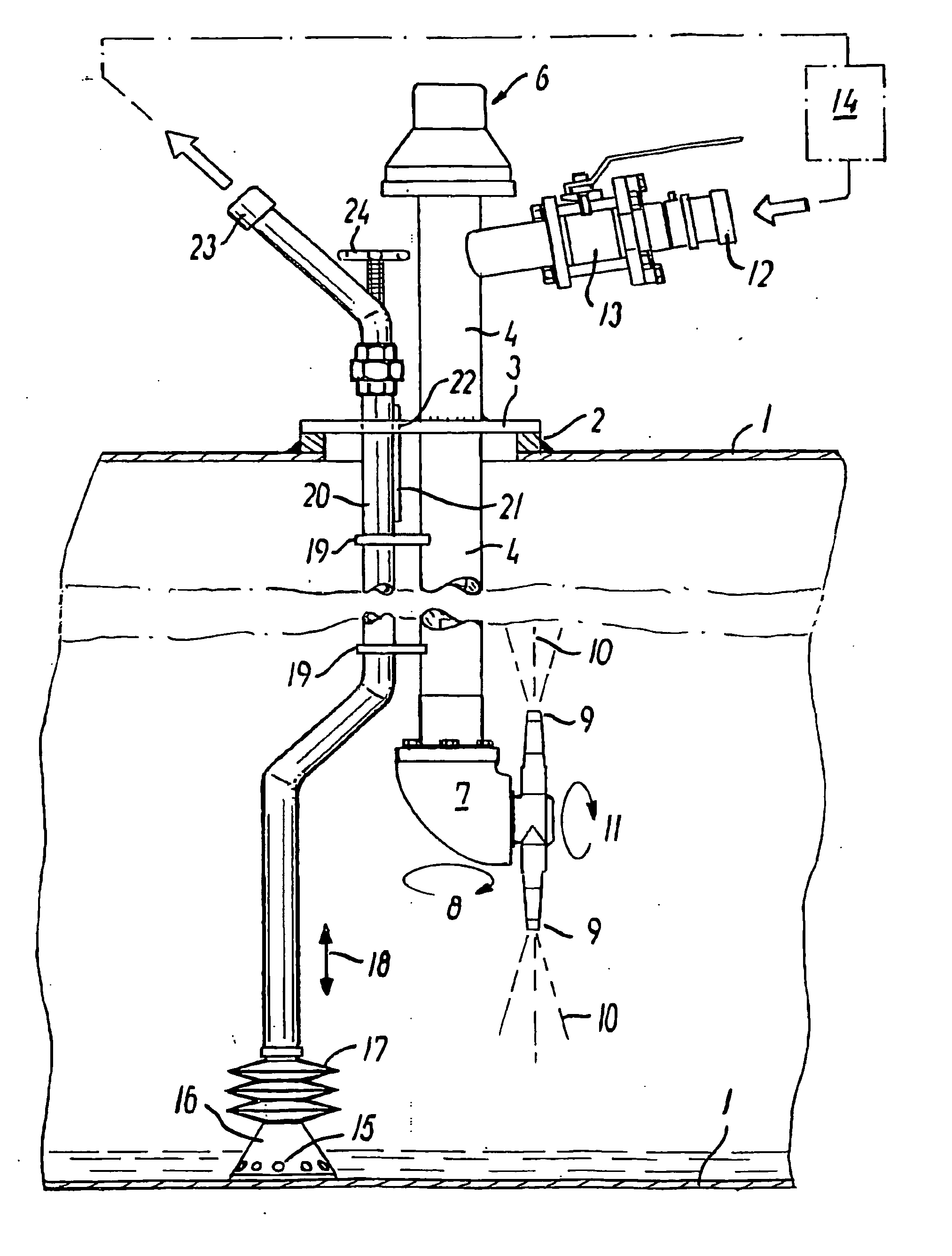
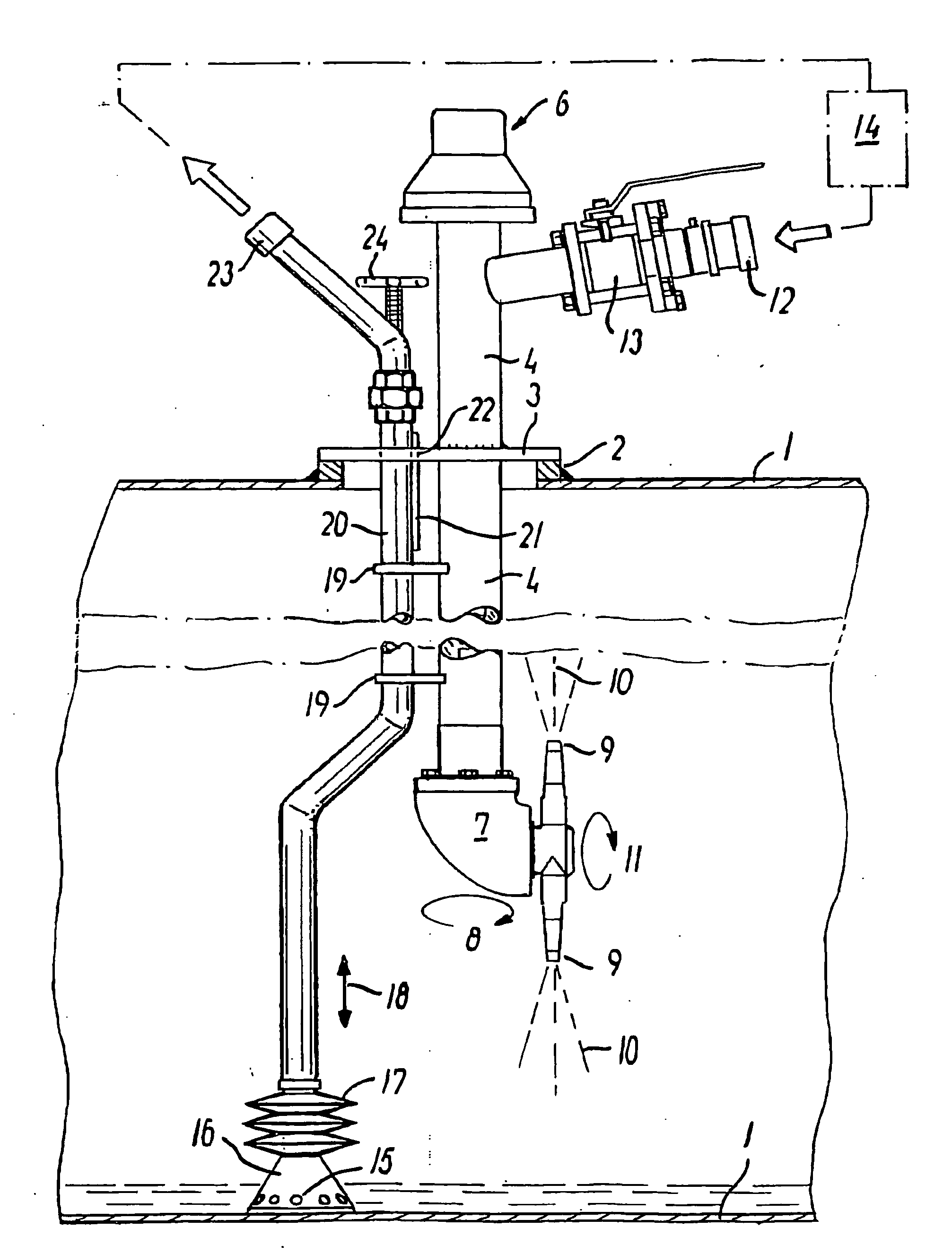
[0012] The drawing shows an example of a preferred embodiment of the equipment according to the invention.

[0013] The tank in which the equipment is mounted is indicated with an upper and lower tank wall 1.

[0014] The top of the tank is formed with a hole at which a flange 2 is mounted.

[0015] A cover 3 is secured to this flange 2. Where the equipment is not mounted, the cover is a so-called closed cover, which is fixedly bolted in a generally known manner.

[0016] When the cleaning equipment is to be mounted, the cover is removed, and the cover 3 shown in the drawing is mounted, through which a cleaning pipe 4 as well as a suction pipe 20 may be passed.

[0017] The cleaning pipe 4 is normally welded to the cover 3, protruding a distance above the cover and such that a drive means (not shown) for a coupling member 6 may be mounted

[0018] Furthermore, a supply stub 12 for the supply of cleaning medium under pressure is provided.

[0019] A valve 13 controls the supply of this medium.

[0020] The ...


PUM


Abstract

By constructing tank cleaning equipment according to the invention such that it comprises a cleaning jetting part (7, 9) as well as a suction part (4), the equipment can work with the same cleaning medium which is recirculated. This saves supply of fresh cleaning medium, and since used medium is thus not discharged, it is not necessary to establish deposit facilities to avoid pollution. Furthermore, this equipment according to the invention may advantageously be used for keeping so-called drilling mud in a mixed and thus ready-to-use state, even when left to stand for an extended period of time in a tank. The nozzle jets (10) thus keep the mud in the tank in a constantly mixed state, and the mud can therefore be sucked through the suction pipe (20) for pumping in the drill pipe, it being ensured that the mud is homogeneous and has a suitable viscosity.

Description

STATE OF THE ART[0001] The invention relates to cleaning equipment for the cleaning of a tank space by means of pipe lowered into the tank space with cleaning equipment comprising a revolving cleaning head with rotating nozzles, and from which cleaning medium is discharged, as well as use of the equipment.[0002] Cleaning equipment of this type is used in particular for the cleaning of various forms of tank spaces for use in process technology, the food industry as well as storage tanks.[0003] Cleaning takes place by means of flushing from rotating and revolving nozzles so that the entire internal surface of the tank space is flushed. Material settled on the tank wall and the cleaning medium must subsequently be pumped out and collected. This cleaning medium with suspended material is frequently a problem, since it must be stored for subsequent cleaning in order to avoid pollution. To this should be added that this cleaning process must be supplied with an uninterrupted flow of clean...

Claims


Application Information

Patent Timeline
Patent Type & Authority Applications(United States)
IPC IPC(8): B08B9/08B08B9/093B63B57/02
CPCB08B9/08B08B9/0933B08B9/0936B63B57/02
Inventor FALSTER-HANSEN, HENRIKELGAARD, RENE VINTHER
Owner ALFA LAVAL TANK EQUIP
Why Eureka
Try Eureka