
Method of calculating and displaying mutual interference in the down direction in a cellular radiotelephone network with a W-CDMA type access

a technology of cellular radiotelephone network and mutual interference, applied in the field of mobile radiotelephony communication system, can solve the problems of increasing interference level, w-cdma system limited by noise, and requiring power control

Inactive Publication Date: 2004-12-02
SOC FR DU RADIOTELEPHONE SFR
View PDF8 Cites 40 Cited by
  • Summary
  • Abstract
  • Description
  • Claims
  • Application Information

AI Technical Summary

Benefits of technology

"The invention is a method for calculating and displaying interference in a cellular radiotelephony network with a W-CDMA type access. The method is designed to better identify and isolate interfering cells, and to optimize power control. The method uses a map-based system to select interfering cells and calculates the interference field based on the power, traffic, and load in the down direction. The invention provides a simple, fast, and operational method for identifying and isolating interfering cells."

Problems solved by technology

With this technique, the interference level increases as the number of mobiles in the cell increases.
Therefore, the W-CDMA system is limited by noise.
Consequently, this system requires control over power.
However, obtaining a statistical position of mobiles is particularly difficult since several draws (Monte Carlo draws) are necessary and these calculations are particularly long.
This method can be adopted for very precise positioning but it may be difficult to use it for a very large network.
Moreover, it is unusable for identifying and isolating the cells with greatest interference, within a group of cells.
Therefore, interference depends more particularly on the power supplied in the down direction.

Method used


Image

  • Method of calculating and displaying mutual interference in the down direction in a cellular radiotelephone network with a W-CDMA type access
  • Method of calculating and displaying mutual interference in the down direction in a cellular radiotelephone network with a W-CDMA type access
  • Method of calculating and displaying mutual interference in the down direction in a cellular radiotelephone network with a W-CDMA type access

Examples


Embodiment Construction

(s)

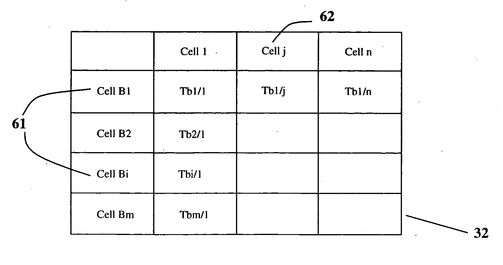
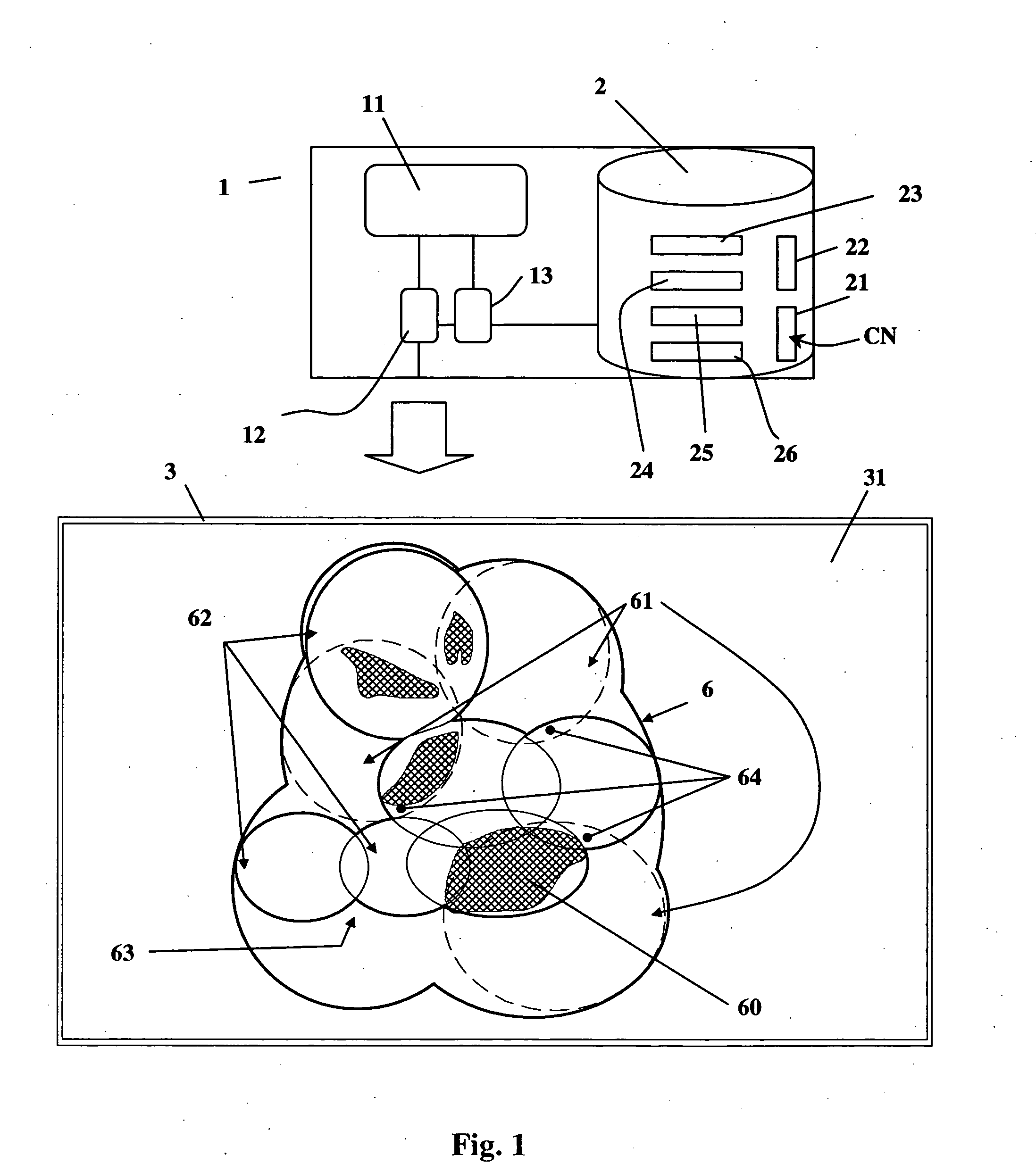
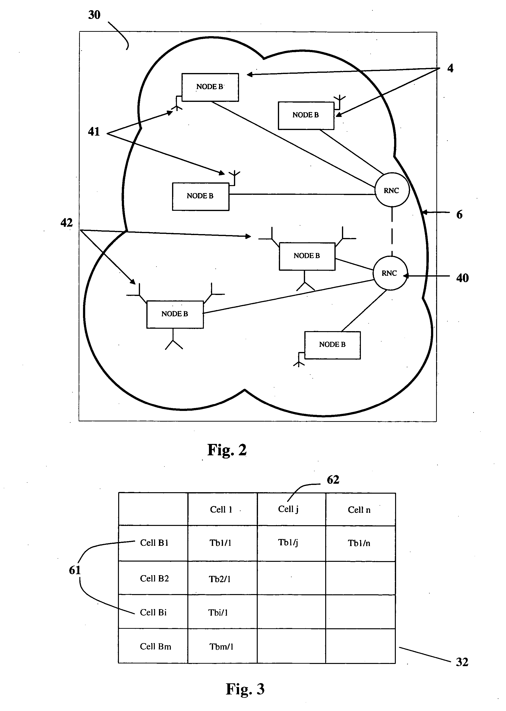
[0048] We will now describe the invention in relation to FIGS. 1, 2 and 5.

[0049] Specifically, in the down direction of a UMTS type radio network or a similar type of network operating with the W-CDMA protocol, any reception or transmission device formed by a Node B (4, FIG. 2) transmits a signal through an antenna (41, 42) on a frequency band common to all mobile terminals of users of this network. FIG. 2 shows an example of a portion (30) of the UMTS type radio access network that the user of the computer system (1) according to the invention can select on the computer system display to study mutual interference between cells. As shown in FIG. 2, a Node B (4) may for example be associated with an omni-directional antenna (41) or at least one sectorial antenna (42) transmitting in a single sector. Communications are routed between the Node B (4) and the core of the network using RNC (Radio Network Controller) elements (40). Each antenna (41, 42) in operation covers a territorial...


PUM


Abstract

The process consists of selecting a sub-set of interfering cells and a sub-set of interfered cells among a set of a radio cells in a network, fixing a plurality of calculation parameters such as threshold levels for signal / interference ratios, parameters related to the power of interfering cells and the traffic channel, then determining the service area of the interfered cells and the area including inter-cell overlaps, then calculating the attenuation of the interfering cell and the attenuation of the serving interfered cell respectively, at each point or pixel in the overlap area. An estimate of the signal / interference ratio is made for each pixel starting from attenuations and parameters. The invention is used to isolate and identify interfering cells and interfered cells. The power in the interfering cells generating an excessive disturbance can thus be adjusted.

Description

[0001] 1. Field of the Invention[0002] This invention relates to the domain of mobile radiotelephony communication systems. This invention relates particularly to a method of calculating and displaying interference generated by a cell or group of cells in the down direction, for the purposes of planning and optimizing a cellular radiotelephony network in which the radio interface is based on a W-CDMA type protocol (Wideband Code Distributed Multiple Access). The invention also relates to a system for implementing the process.[0003] 2. Brief Description of Related Developments[0004] A UMTS (Universal Mobile Telecommunications System) type radio network is distinguished from a Global System with Mobile communications (GSM) particularly due to the new wideband code distributed multiple access (W-CDMA) technique. The multiple access technique adopted for the radio interface between a user equipment and Node B is one of the essential aspects of cellular networks. W-CDMA was chosen due to...

Claims


Application Information

Patent Timeline
Patent Type & Authority Applications(United States)
IPC IPC(8): H04W16/18
CPCH04W16/18
Inventor FATTOUCH, IMADHUBERT, JEAN-MARCVINCENT, FRANCOIS
Owner SOC FR DU RADIOTELEPHONE SFR
Learn More