
Endoscopic auditory canal cleaning apparatus

Inactive Publication Date: 2004-12-09
CODEN
View PDF16 Cites 25 Cited by
  • Summary
  • Abstract
  • Description
  • Claims
  • Application Information

AI Technical Summary

Benefits of technology

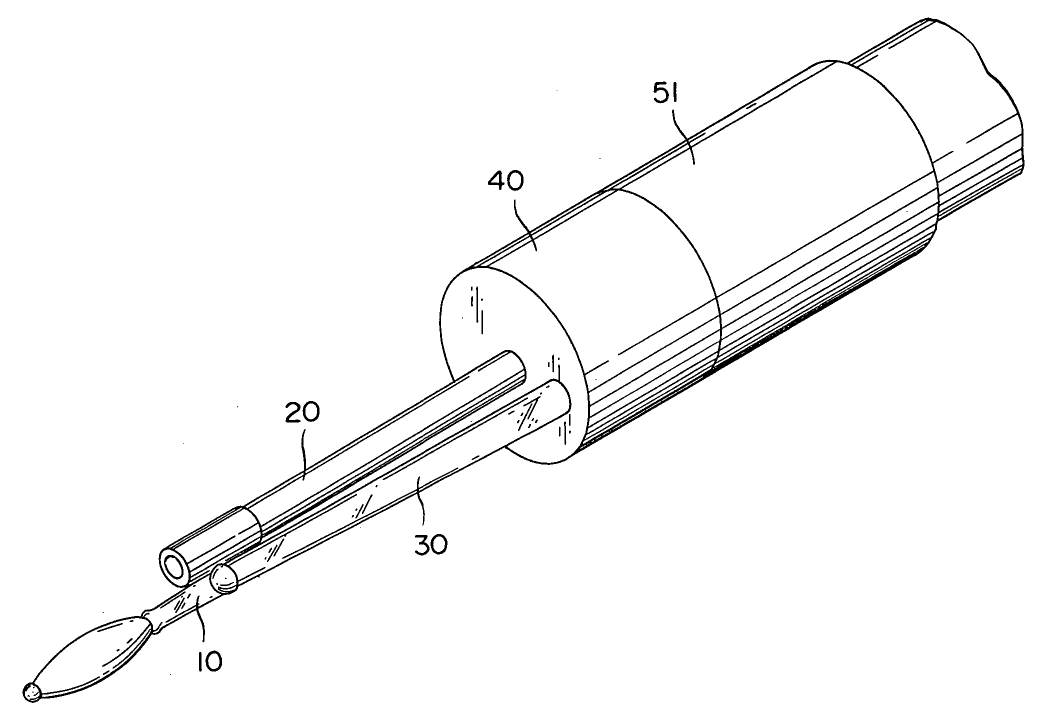
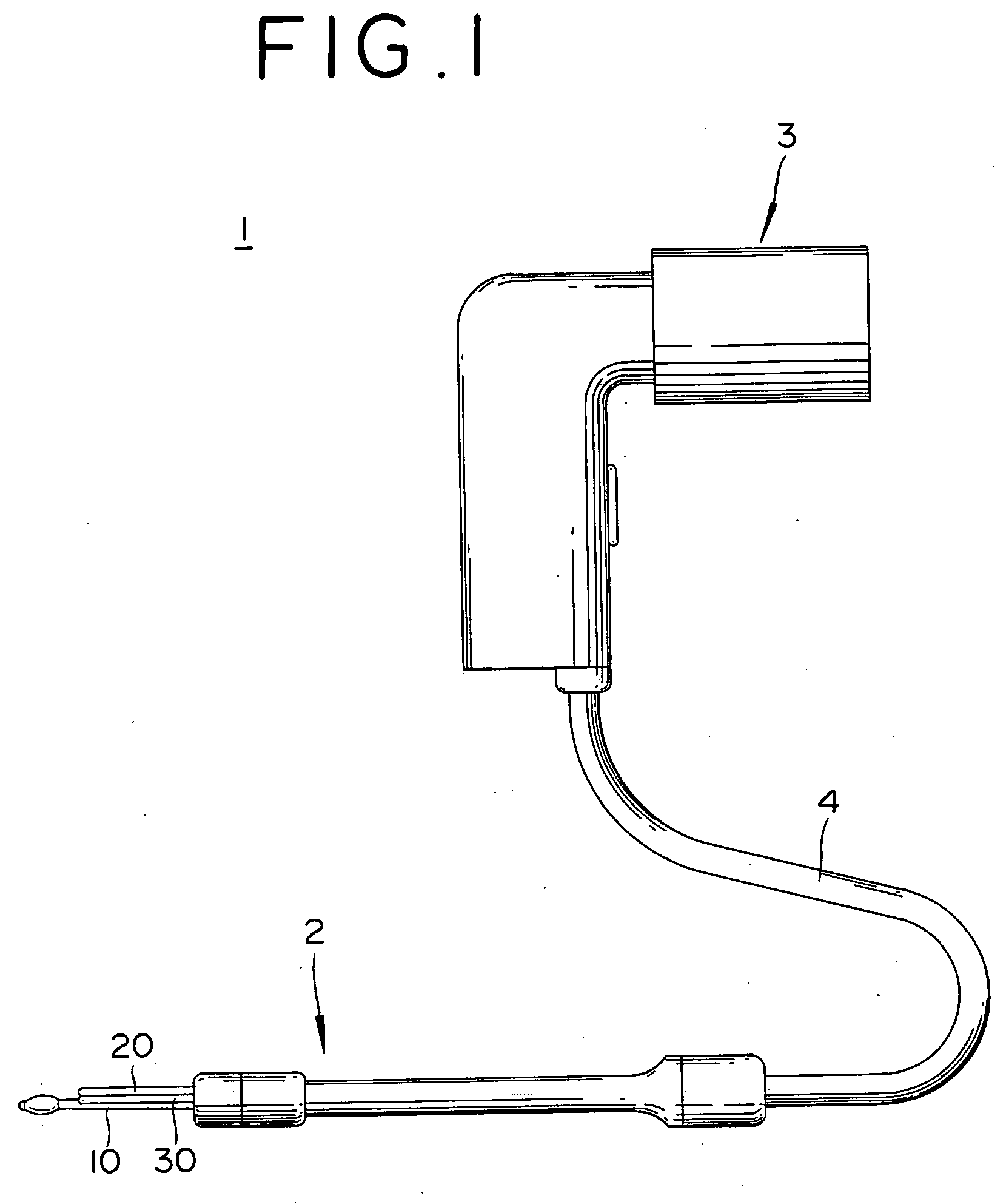
[0016] According to the endoscopic auditory canal cleaning apparatus of this invention, the interior of the auditory canal can be radiated with the light emitted at the leading terminal of the ear picking main body and the image of the interior of the auditory canal can be incorporated by the image incorporating means. Here, the holding means for holding the ear picking main body can be freely rotated around the an image incorporating means as the central axis. It is, therefore, made possible to clean the interior of the auditory canal by freely rotating the ear picking main body alone while keeping the image fixed in one direction. Since the direction of the image is fixed, the interior of the auditory canal can be cleaned safely and infallibly without losing sight of the objective such as cerumen.

Problems solved by technology

The act of rummaging the interior of the ear in strict accordance with intuition, however, cannot be trusted to attain removal of cerumen actually as expected and, on account of its possibility of inflicting injury to the interior of the auditory canal, cannot be regarded as safe.
When the cleaning is aimed at removing wet cerumen, however, the cerumen which is in a semiliquid or liquid state and is devoid of a constant form cannot be scooped very satisfactorily with the scraping part of the shape of a spoon.
If the wet cerumen is scooped at all, it cannot be easily removed thoroughly because it partly survives the removal.
By merely replacing this scraping part with the cotton swab, it is not made possible to guide the light to the leading terminal of the cotton swab on which the cotton is wound.

Method used


Image

  • Endoscopic auditory canal cleaning apparatus
  • Endoscopic auditory canal cleaning apparatus
  • Endoscopic auditory canal cleaning apparatus

Examples


second embodiment

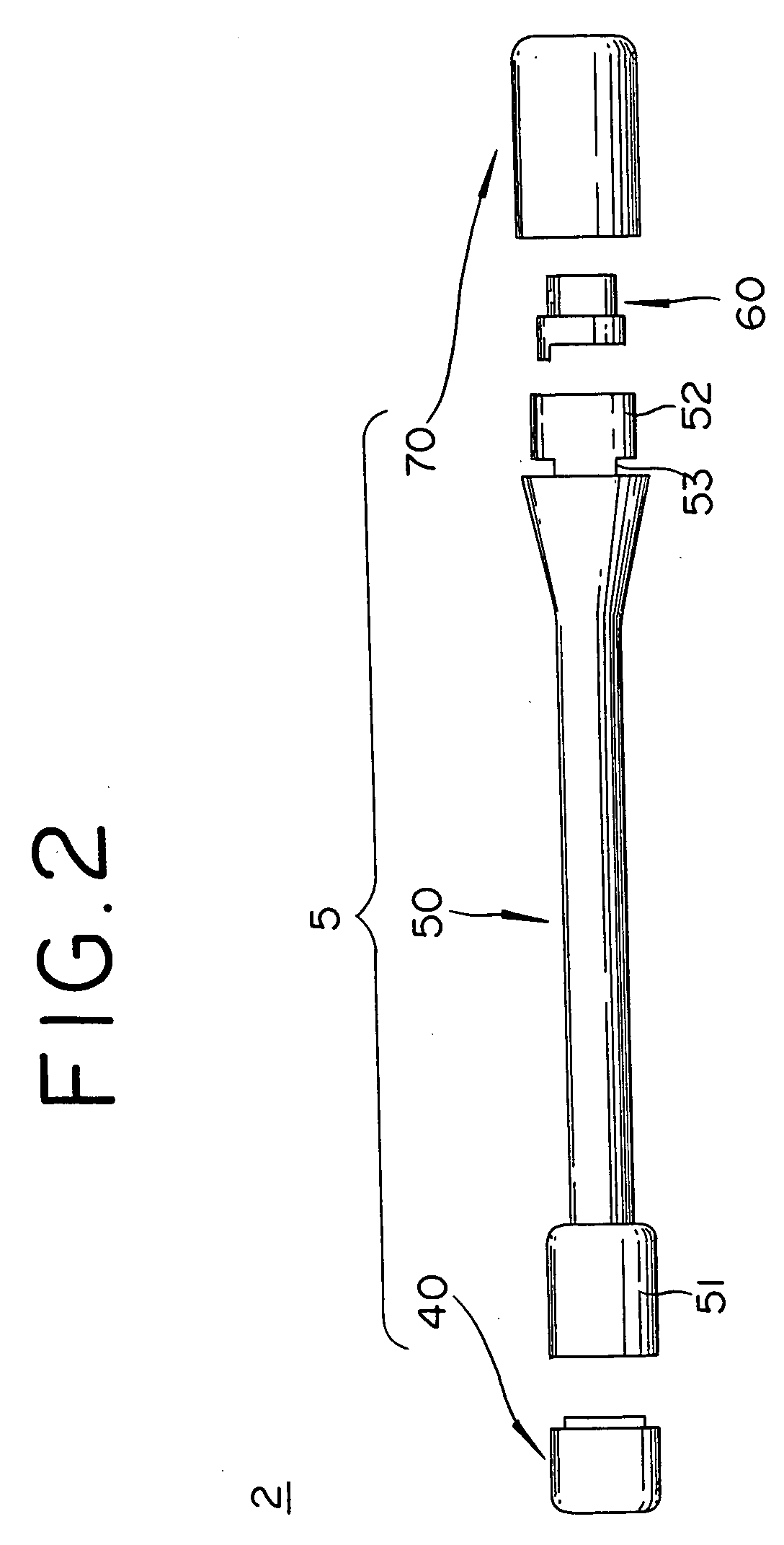
[0135] In the first embodiment cited above, the ear picking main body 10 is removably attached to the ear pick mounting part 40 in the pattern of convexo-concave union. Owing to the union in this convexo-concave pattern, the ear picking main body 10 cannot rotate in itself. During the cleaning of the interior of the auditory canal, therefore, the same portions, particularly outside portions, of the fibrous part 92 of the ear picking part 90 are used frequently. Since the portions which are used frequently get dirty early, the intervals for replacing the ear picking part 90 become proportionately short. Notwithstanding this fact, the inside portions of the ear picking part 90 remain nearly undefiled. The ear picking part 90, therefore, proves uneconomical in the respect that it cannot be wholly used evenly and it is therefore inevitably replaced totally owing to the extreme defilement possibly sustained partly.

[0136] The second embodiment, with a view to overcoming the problem encoun...


PUM


Abstract

An endoscopic auditory canal cleaning device is provided which is capable of properly removing wet cerumen while keeping the interior of an auditory canal radiated with ample light. This endoscopic auditory canal cleaning device has a construction comprising the following components: A light source which generates light; an ear picking main body which is so formed as to guide the light generated by the light source to the leading terminal thereof; an ear picking part which is furnished with a surface layer formed of a fibrous material and adapted to be disposed in the ear picking main body by exposing the leading terminal mentioned above; an image incorporating means which incorporates an image of the interior of the auditory canal radiated with the light guided to the leading terminal of the ear picking main body; a display means which displays an image taken in by the image incorporating means, and a holding means which is furnished with a hollow mouth for allowing penetration therethrough of the image incorporating means and allowed to rotate freely around the image incorporating means as the central axis with the ear picking main body kept in a held state.

Description

[0001] 1. Field of the Invention[0002] This invention relates to an endoscopic auditory canal cleaning apparatus which is capable of removing cerumen safely and infallibly.[0003] 2. Description of the Prior Art[0004] Since no one can look into the interior of one's own auditory canal, the practice of cleaning the auditory canal by rummaging the interior of the auditory canal on the principle of trial and error has been in vogue to date. The act of rummaging the interior of the ear in strict accordance with intuition, however, cannot be trusted to attain removal of cerumen actually as expected and, on account of its possibility of inflicting injury to the interior of the auditory canal, cannot be regarded as safe.[0005] As a solution for this problem, an endoscopic auditory canal cleaning apparatus which enables the user to clean the interior of the auditory canal while continuing his observation of the situation of the interior of the auditory canal (disclosed in Japanese Patent Pub...

Claims


Application Information

Patent Timeline
IPC IPC(8): A47K7/00A61B1/227A61B1/233A61F11/00
CPCA61B1/227A61F11/006
Inventor KODA, YOSHIHARUKODA, KOJIRO
Owner CODEN
Learn More