Communications system and method for synchronizing a communications cycle

a communication system and communication cycle technology, applied in the direction of generating/distributing signals, programme control, instruments, etc., can solve problems such as unsatisfactory results at the subscriber

Active Publication Date: 2004-12-09
SIEMENS AG
View PDF7 Cites 233 Cited by
  • Summary
  • Abstract
  • Description
  • Claims
  • Application Information

AI Technical Summary

Benefits of technology

0011] The object of the invention is thus to create an improved method for synchronization of a communication cycle, an improved communication node and also an improved communication system and automation system and a corresponding computer program product.

Problems solved by technology

This is referred to as realtime-critical data or realtime-critical data traffic since, if the data does not arrive at its intended destination at the right time this can produce undesired results at the subscriber.

Method used


Image

  • Communications system and method for synchronizing a communications cycle
  • Communications system and method for synchronizing a communications cycle
  • Communications system and method for synchronizing a communications cycle

Examples


Embodiment Construction

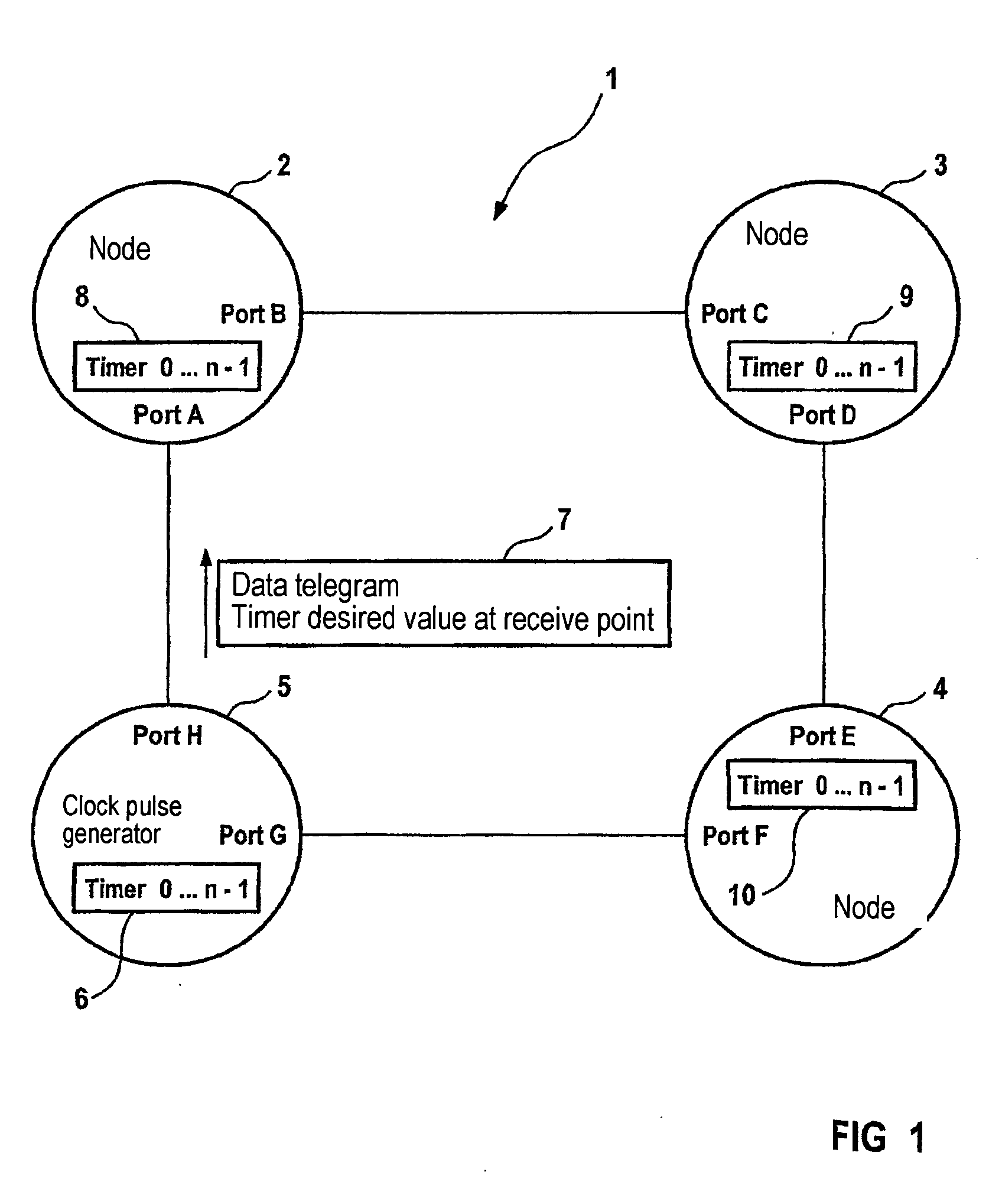
[0020] FIG. 1 shows a network 1 with communication nodes 2, 3, 4 and 5. Communication node 5 is a clock generator node which provides the reference time base for synchronization of the time bases in the other nodes of network 1. The reference clock pulse generator time base of communication node 5 is generated by a timer 6 which, by timing with a local clock of communication node 5, constantly counts from 0 to n-1.

[0021] The communication node 5 is used to create a data telegram 7 for node 2. The data telegram 7 contains the desired value of the time base of node 2 at the point at which the data telegram is received.

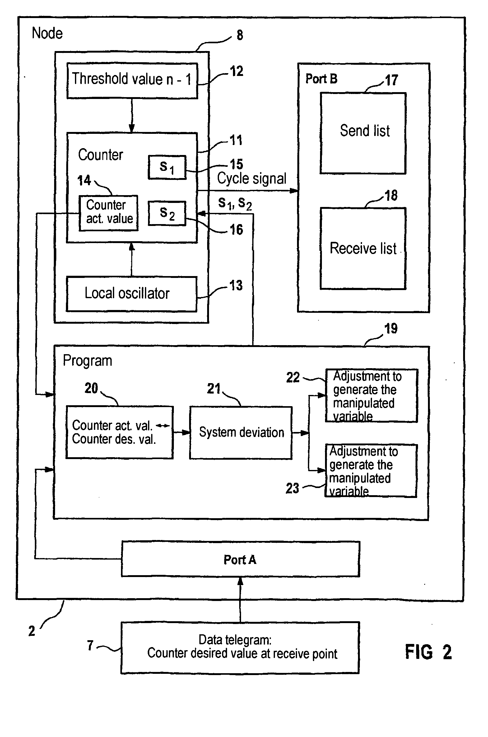
[0022] The time base of node 2 is realized by a timer 8, which basically has the same structure as the timer 6 of the communication node 5. The timer 8 has its own local clock for timing of the counter of the timer which is independent of the clock of the communication node 5. When node 2 is switched on timer 8 is thus asynchronous with timer 6. After an initial synchron...


PUM


Abstract

The invention relates to a method for synchronizing a communications cycle and a communications node in a network. Said node comprises: devices for receiving a desired value for a time base of a communications cycle of the communications node in a communications link to an additional communications node of the network; devices for determining a system deviation between the desired value and an actual value of the time base; and a device for generating a manipulated variable for correcting the time base in accordance with the system deviation.

Description

[0001] This application is the US National Stage of International Application No. PCT / DE02 / 03437, filed Sep. 13, 2002 and claims the benefit thereof. The International Application claims the benefits of German application No. 10147422.9 filed Sep. 26, 2001, both applications are incorporated by reference herein in their entirety.[0002] The invention relates to a communication system and method for synchronization of a communication cycle, especially for use in automation systems.BACKGROUND OF INVENTION[0003] Various methods and systems for establishing communication connections between the subscribers of a data network are known from the prior art. Bus systems by which every subscriber can directly address every other subscriber of the data network are in widespread use. Furthermore switchable data networks are known in which what are referred to as point-to-point connections can be established, i.e. a subscriber can only reach all other subscribers of the switchable data network in...

Claims


Application Information

Patent Timeline
Patent Type & Authority Applications(United States)
IPC IPC(8): G06F1/14H04J3/06
CPCG05B2219/25479G06F1/14H04J3/0655
Inventor ARNOLD, JOHANNBERNECKER, HERBERTBRUCKNER, DIETERGOTZ, FRANZ-JOSEFKLOTZ, DIETERKRAUSE, KARL-HEINZMULLER, CHRISTIANESCHEITHAUER, GERHARDSCHIMMER, JURGEN
Owner SIEMENS AG
Why Eureka
Try Eureka