
Stereoscopic display device and method

Inactive Publication Date: 2004-12-16
KK TOSHIBA
View PDF2 Cites 62 Cited by
  • Summary
  • Abstract
  • Description
  • Claims
  • Application Information

AI Technical Summary

Benefits of technology

[0029] The present invention has been made in view of the above circumstances and an object thereof is to provide a stereoscopic display device which can obtain a correct perspective projection image which has no distortion or has a reduced distortion in one-dimensional IP system (a vertical disparity discarding system).

Problems solved by technology

As a stereoscopic motion picture display device of such a type, there is known one using a principle of holography, which is difficult to be put in a practical use.
In the binocular system, however, there are severe drawbacks that an image is not viewed stereoscopically at positions except for a defined position and a viewing zone is very narrow, that an image appears as a reversed stereoscopic view (pseudoscopy), namely, an abnormal image such that a depth are viewed in a reversed manner when the image is seen at a position moved by a interpupilliary distance (IPD) in left and right directions.
Further, in the multiview system, the problem about the pseudoscopy still remains.
However, since an amount of image information to be processed increases by leaps and bounds as compared with the multiview system, which results in difficulty in realization.
In such a system, however, since the amount of image information to be processed increases by leaps and bounds, it is difficult to realization the system.
In the IP system which also includes a vertical disparity, namely, a two-dimensional IP system, however, since the amount of image information to be processed increases by leaps and bounds it is difficult to realize such a system.
However, the viewing zone in front and rear directions is originally narrow in the multiview system, which does not constrain the viewing zone.
However, the 3-D image can not be seen correctly up to both ends of the screen.
In some literatures or documents lacking in theoretical strictness, there is a description that the both, are identical to each other, but these descriptions are erroneous.
Therefore, it is difficult to discriminate between the image plane and the focal plane regarding the precision and it is also difficult to make discrimination about whether there is presence or absence of convergence of beams in the viewing distance.
It is thought that, when a computation program is created skillfully, the amount of computation itself is not so difficult from that in the multiview system, but a procedure for creation of the program becomes very complicated.
However, an image appearing in this producing method results in a perspective projection in a horizontal direction and an orthographic projection in a vertical direction.
Accordingly, when the vertical direction and the horizontal direction are combined, there occurs a problem that an image is distorted except for a predetermined viewing distance.
On the other hand, in the one-dimensional IP, there is a merit that a front and rear range where an image appears to be stereoscopic is wide, but this merit can not be eventually utilized sufficiently due to distortion occurrence.
As described in detail, since there is not a vertical disparity in the one-dimensional IP system, there occurs a problem that a perspective projection image in a vertical direction must be displayed on the assumption of a certain viewing distance and the image is distorted except for at the distance.

Method used


Image

  • Stereoscopic display device and method
  • Stereoscopic display device and method
  • Stereoscopic display device and method

Examples


first embodiment

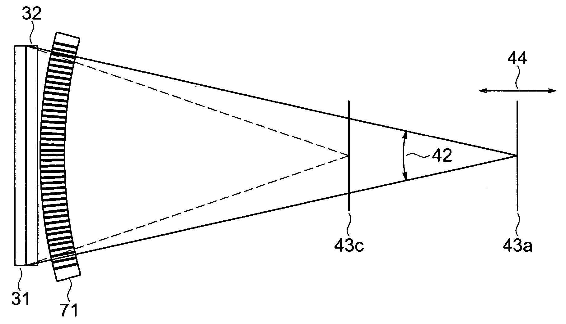
[0063] A stereoscopic display device according to the first embodiment of the present invention will be explained with reference to FIG. 1 to FIG. 12. The stereoscopic display device according to this embodiment is provided with a liquid crystal panel 31 serving as a flat display device and a parallax barrier 32, as illustrated in FIGS. 1 and FIG. 4. FIG. 1(a) is a front view of the liquid crystal panel 31 and the parallax barrier 32, FIG. 1(b) is a plan view illustrating an image arrangement of a stereoscopic display device according to the embodiment, and FIG. 1(c) is a side view illustrating the image arrangement of the stereoscopic display device according to the embodiment. FIG. 4 is a transmission view illustrating the image arrangement of the stereoscopic display device according to the embodiment.

[0064] As far as the display device 31 is constituted such that pixels whose positions are defined within a display plane are arranged flatly in a matrix manner, it may be any one o...

second embodiment

[0083] Next, a second embodiment of the present invention will be explained with reference to FIG. 1 to FIG. 19. A stereoscopic display device of the embodiment is constituted by further adding a function for inputting a viewing distance and displaying an image corresponding to the input viewing distance to the stereoscopic display device of the first embodiment. Inputting means for the viewing distance may be such a manual inputting device as a button, a knob, a software switch or the like, and it may be constituted so as to dispose the viewing distance sensor (the observer position detector) 73 on the liquid crystal panel 31 to perform automatic detection and conduct feedback of the detected data to an image to be displayed, for example, as illustrated in FIG. 4. As the viewing distance sensor 73, for example, an autofocus measuring element used in a camera can be utilized.

[0084] In this connection, besides the detection of the position of the observer, the position of a mouse can...

third embodiment

[0092] A third embodiment of the present invention will be explained with reference to FIG. 13 to FIG. 15. A stereoscopic display device of this embodiment is constituted by providing a vertical direction indicator 72 which can detect that a viewpoint 43 of an observer is positioned out of a viewing zone in up and down directions and in front and rear directions in a stereoscopic display device of a one-dimensional integral photography system, as illustrated in FIG. 13. That is, the stereoscopic display device of the embodiment is provided with an alarming function which detects such a fact that the viewpoint 43 of the observer is positioned out of the viewing zone in up and down directions and in front and rear directions and outputs alarm. Incidentally, FIG. 13 is a view illustrating a constitution of the stereoscopic display device provided with the vertical direction indicator according to the embodiment. In this connection, in FIG. 13, reference numeral 41 denotes a horizontal ...


PUM


Abstract

In a one-dimensional IP (vertical disparity discarding system), it is made possible to obtain a perspective projection image with no distortion or reduced distortion. A stereoscopic display device is provided with a display device including a display plane in which pixels are arranged flatly in a matrix shape; and a parallax barrier including a plurality of apertures or a plurality of lenses and being configured to control directions of rays from the pixels such that a horizontal disparity is included but a vertical disparity is not included. A horizontal direction pitch of the parallax barrier is integer times a horizontal pitch of the pixels, the display plane of the display device is divided so as to correspond to elemental images for respective apertures or the lenses of the parallax barrier, and an image whose vertical direction corresponds to a perspective projection in a fixed viewing distance and whose horizontal direction corresponds to an orthographic projection is divided and arranged for respective columns of the pixels.

Description

[0001] This application is based upon and claims the benefit of priority from prior Japanese Patent Application No. 2003-90738, filed on Mar. 28, 2003 in Japan, the entire contents of which are incorporated herein by reference.[0002] 1. Field of the Invention[0003] The present invention relates to a stereoscopic display device and a stereoscopic display method.[0004] 2. Related Art[0005] As a stereoscopic video image display device which allows display of a motion picture, a so-called three-dimensional display, ones of various systems have been known. In recent years, particularly, a display device of a flat panel type employing a system where dedicated eyeglasses or the like are not required is demanded highly. As a stereoscopic motion picture display device of such a type, there is known one using a principle of holography, which is difficult to be put in a practical use. A system where a beam controlling element is installed in front of a display panel (a display device) whose pi...

Claims


Application Information

Patent Timeline
IPC IPC(8): G02B30/27G02B30/30G03B35/00H04N13/00
CPCG02B27/2214G03B35/24H04N13/0404H04N13/0409H04N13/305H04N13/31G02B30/27G02B30/30G03B35/00
Inventor SAISHU, TATSUOHIRAYAMA, YUZO
Owner KK TOSHIBA
Features
  • Generate Ideas
  • Intellectual Property
  • Life Sciences
  • Materials
  • Tech Scout
  • Unparalleled Data Quality
  • Higher Quality Content
  • 60% Fewer Hallucinations
Learn More