
Image processing apparatus, image processing process and program

a technology of image processing and image processing equipment, applied in the field of image processing equipment and image processing process, can solve the problems of large power, image deterioration in many cases, and long time-consuming image formation

Inactive Publication Date: 2004-12-30
CANON KK
View PDF22 Cites 2 Cited by
  • Summary
  • Abstract
  • Description
  • Claims
  • Application Information

AI Technical Summary

Benefits of technology

[0032] By generating independent multi-level data corresponding to plural species of dots (different in at least one of a diameter or a density) which take on an identical hue (e.g., cyan or magenta) but have different powers), it becomes possible to effect minute control as to proper use for each species of dots. In addition, on the basis of a relationship between multi-level data for the respective dots for each target pixel, data relating to an amount of generation (generation amount) of the plural species of dots (e.g., the number of generation of dots) are determined. As a result, it is possible to not only reduce a probability of overlapping of the plural species of dots within the same pixel but also realize such an arrangement of the plural species of dots that a good visual characteristic is attained even in the case where the plural species of dots are co-present.

Problems solved by technology

On the other hand, a dot having a large dot diameter is liable to be visible to human eye, so that its power is large.
Further, in order to form an image by using only the small diameter dot, a large number of dots are required, thus taking much time for image formation.
More specifically, when an image s formed only of the small diameter dot, an irregularity in position of formation of dot on a recording medium sensitively leads to image deterioration in many cases.
However, in such a recording apparatus which effects image formation by using dots which take on an identical hue but have different powers, image problems have arisen in some cases at a boundary portion between a high brightness image portion where image formation may preferably be performed by using only the small power dot and a low brightness potion where image formation may preferably be performed by using not only the small power dot but also the large power dot.
Representative examples of the image problems include a problem that the large power dot disposed in mixture with the lower power dot becomes obtained on the recording medium, thus causing a relatively large granulation (compared with other density portions), and a problem that the small power dot and the large power dot are arranged side by side to cause an apparent frame or edge.
As a result, the effect of alleviating the image problems becomes small in some cases.
However, in this method, there arises a problem such that there is a low degree of flexibility in control of the large and small power dots.
Further, it is impossible to control, e.g., a proportion of the large and small power dots.
The small dot is generated sensitive to an accuracy of dot formation position of the recording apparatus, so that it is liable to cause a streak, an unevenness, a texture or the like.
In the case where the relatively large and small dots overlap each other, a larger amount of ink attaches onto the same portion on the recording medium, thus increasing granulation.
Further, it is possible to make the streak, unevenness and texture, which are caused in the case of lack of positional accuracy in formation of the same dot and are much liable to occur as the density of the small dot becomes higher, less visible to eyes by the formation of the large dot.
Further, in addition to the highlight image, also in a relatively high dot density image, a concentration of the same species of dots is not readily caused to occur.

Method used


Image

  • Image processing apparatus, image processing process and program
  • Image processing apparatus, image processing process and program
  • Image processing apparatus, image processing process and program

Examples


example 2

[0132] In the second generation step of the method of Example 1, data relating to an amount of generation of the plural species of dots with respect to the target pixel are generated so as to decrease a probability of overlapping of the plural species of dots, different in at least one of a density and a diameter, at the target pixel.

example 3

[0133] In the method of Example 1 or 2, wherein the number of dots to be formed at the target pixel is determined on the basis of the data generated in the second generation step.

example 4

[0134] In the method of any one of Examples 1-3, the first generation step includes:

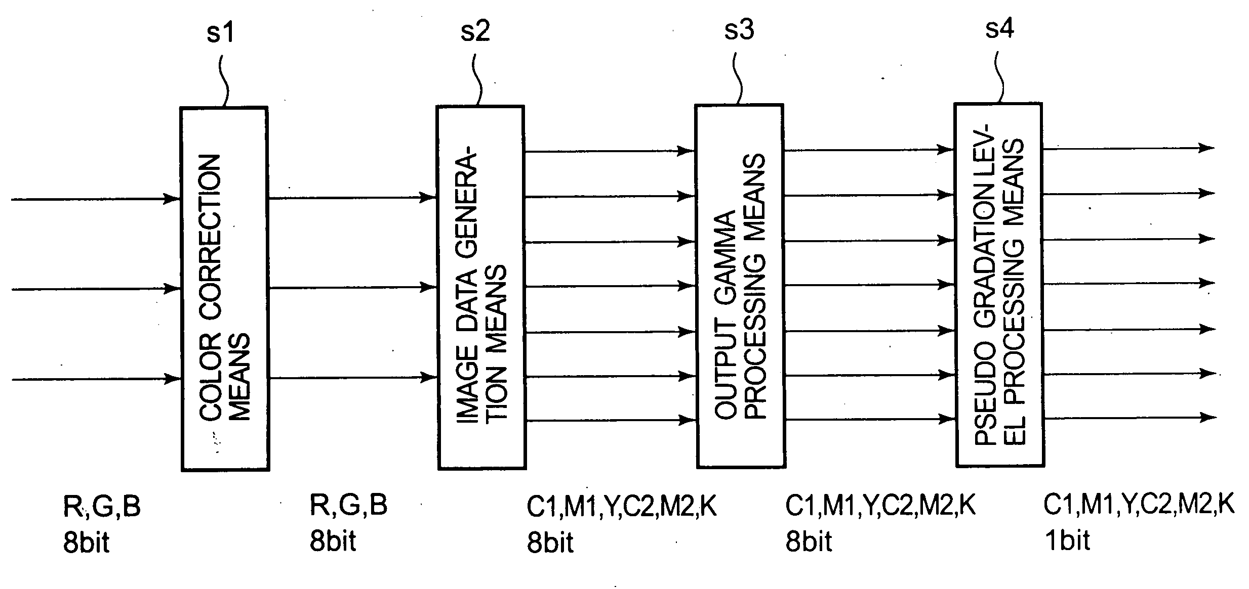
[0135] (A) a conversion step of converting input image data (e.g., RGB data) into independent data (e.g., I0, I1) corresponding to the plural species of dots,

[0136] (B) an addition step of adding an error (e.g., E0, E1) obtained through a predetermined manner to the converted data (e.g., I0, I1), and

[0137] (C) a step of generating independent multi-level data (e.g., g0, g1) corresponding to the plural species of dots by quantizing the data (e.g., I'0, I'1) obtained in the addition step. The error (e.g., E0, E1) is calculated from the data (e.g., O'0, O'1) obtained on the basis of the data (e.g., O0, O1) obtained in the generation amount of the plural species of dots, generated in the second generation step.


PUM


Abstract

In an image processing method, on the basis of input image data with respect to a target pixel, independent multi-level data (g0, g1) corresponding to respective plural species of dots which are different in at least one of a density and a diameter are generated, and then data (O0, O1) relating to an amount of generation of the dots with respect to the target pixel are generated on the basis of a relationship between the generated independent multi-level data (g0, g1) corresponding to the plural species of dots. The image processing method is effective in performing design having a high degree of flexibility in proper use of a relatively high power dot (high density dot or large dot) and a relatively low power dot (low density dot or small dot) and can realize obviation or alleviation of an occurrence of granulation or an apparent frame caused due to the relatively high power dot.

Description

FIELD OF THE INVENTION AND RELATED ART[0001] The present invention relates to an image processing apparatus, an image processing method, and a program, for performing image data processing in order to effect image formation by forming dots having different powers (dots different in at least one of a diameter or a density) on a recording medium by a recording apparatus.[0002] In a recording apparatus for effecting color image formation, image formation has ordinarily performed by forming dots of three hue system of cyan, magenta and yellow or four hue system of cyan, magenta, yellow, and black.[0003] In recent years, in such a recording apparatus which effects display by forming the dots on the recording medium, image formation has been effected by forming dots which take on an identical hue but have different powers.[0004] Herein, the power refers to an image forming ability of a dot formed on a recording medium, i.e., a power conspicuous to human eye. For example, a dot having a sm...

Claims


Application Information

Patent Timeline
Patent Type & Authority Applications(United States)
IPC IPC(8): B41J2/52B41J2/01H04N1/40H04N1/405H04N1/52H04N1/60
CPCH04N1/40087H04N1/4057B41J2/04593B41J2/205B41J2/52
Inventor NISHIKORI, HITOSHIOTSUKA, NAOJITAKAHASHI, KIICHIROIWASAKI, OSAMUTESHIGAWARA, MINORUYAZAWA, TAKESHICHIKUMA, TOSHIYUKI
Owner CANON KK
Learn More