Vector transient reflow of lead free solder for controlling substrate warpage

a technology of transient reflow and lead free solder, which is applied in the field of system and method for reflowing leadfree solder, to achieve the effect of enhancing the ease of soldering to the pads

Inactive Publication Date: 2005-01-06
SYNAPTICS INC
View PDF49 Cites 16 Cited by
  • Summary
  • Abstract
  • Description
  • Claims
  • Application Information

AI Technical Summary

Benefits of technology

[0007] Preferably, the circuit conductors on the substrate are copper. Selected regions of the conductors referred to as component pads are provided with a surface finish such as tin or immersion silver to enhance the ease of soldering to the pads. The spaces between the conductor regions of the substrate may be filled with electrically isolated regions of copper having the same thickness as the conductor regions. These copper areas further shield the substrate during reflow by selectively absorbing heat during the reflow process.

Problems solved by technology

Additionally, a process for reflowing lead-free solder disposed between a substrate and a plurality of electronic components thereon is not addressed by the prior art and is therefore needed.

Method used


Image

  • Vector transient reflow of lead free solder for controlling substrate warpage
  • Vector transient reflow of lead free solder for controlling substrate warpage
  • Vector transient reflow of lead free solder for controlling substrate warpage

Examples


Embodiment Construction

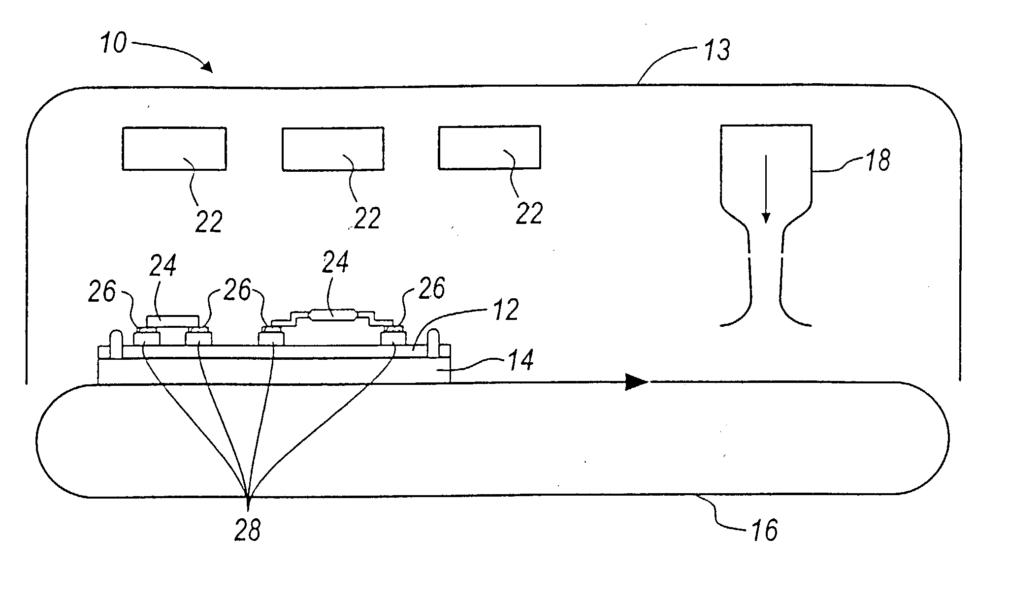
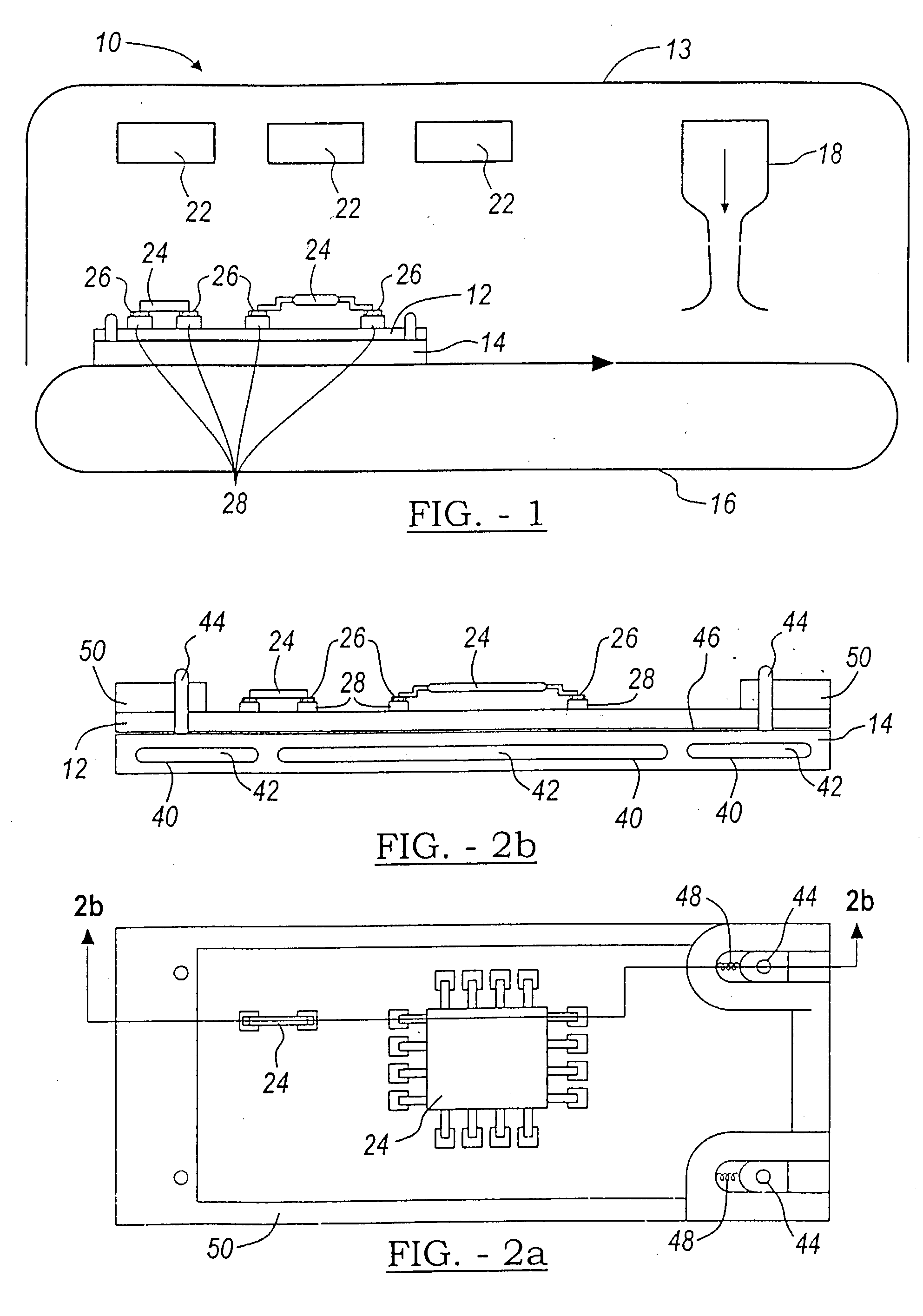
[0023] A system 10 for reflowing solder to electrically interconnect electronic components to a flexible, semi-flexible or rigid substrate 12 is illustrated in FIG. 1, in accordance with the present invention. Further, system 10 includes a pallet 20 that provides a means to mount circuit components on substrate 12 without degrading the material properties of the substrate. System 10 additionally includes a reflow oven 13, a conveyor system 16, a gas nozzle 18 and a pallet 20. The reflow oven has a plurality of heaters 22 to pre-heat the substrate 12 to a desired temperature. Conveyor system 16 is configured in a conventional manner to cooperatively receive pallets 14 for movement through the reflow oven 13.

[0024] Pallet 14 in an embodiment of the present invention is, preferably, a phase-transition pallet 14 for reflowing solder paste to interconnect electronic components 24 to substrates 12. Phase-transition pallet 14 is configured to support substrate 12 and cooperates with conve...


PUM

PropertyMeasurementUnit
angleaaaaaaaaaa
angleaaaaaaaaaa
angleaaaaaaaaaa

Abstract

A system and method for reflowing lead-free solder to interconnect a plurality of electronic components to a substrate is disclosed. The system includes an oven for preheating the substrate and the plurality of electronic components disposed thereon, and a supplemental heat source disposed in the oven for providing additional heat energy to reflow the solder.

Description

TECHNICAL FIELD [0001] The present invention relates to a system and method for reflowing lead-free solder to electrically connect electronic components to a substrate. BACKGROUND OF THE INVENTION [0002] It is well known in the art to mount electronic components to rigid and printed circuit boards. Typically, solder paste is applied to conductor pad regions on the rigid or substrate. Components are then placed with their terminals contacting the solder paste in the pad regions. The substrate is then exposed to relatively high temperatures to activate the solder paste which melts and then solidifies to bond and electrically connect the components onto the substrate. [0003] A technique for mounting components onto flexible polyester substrates with low softening temperatures is taught by Annable in U.S. Pat. No. 5,898,992. The flexible substrate is fixed to a carrier support member. A cover is placed over the substrate. The cover has openings corresponding to component locations and w...

Claims


Application Information

Patent Timeline
Patent Type & Authority Applications(United States)
IPC IPC(8): B23K1/008B23K3/047H05K3/34
CPCB23K1/008B23K3/0478H05K2203/111H05K2203/0557H05K2203/081H05K3/3494
Inventor GOENKA, LAKHI N.SINKUNAS, PETER J.SCHMIDT, LARRY N.MOSS, SHERWIN T.
Owner SYNAPTICS INC
Why Eureka
Try Eureka