Fuel injector assembly

a fuel injector and assembly technology, applied in the direction of fuel injection apparatus, fuel feed system, spraying apparatus, etc., can solve the problems of reducing the efficiency of the fuel injector, and reducing the time between injection cycles, so as to eliminate or minimize the latching effect, minimize fluid accumulation, and minimize the effect of fluid accumulation

a fuel injector and assembly technology, applied in the direction of fuel injection apparatus, fuel feed system, spraying apparatus, etc., can solve the problems of reducing the efficiency of the fuel injector, and reducing the time between injection cycles, so as to eliminate or minimize the latching effect, minimize fluid accumulation, and minimize the effect of fluid accumulation

US20050001055A1Inactive Publication Date: 2005-01-06SIEMENS DIESEL SYST TECH

Image

  • Fuel injector assembly
  • Fuel injector assembly
  • Fuel injector assembly

Examples


Embodiment Construction

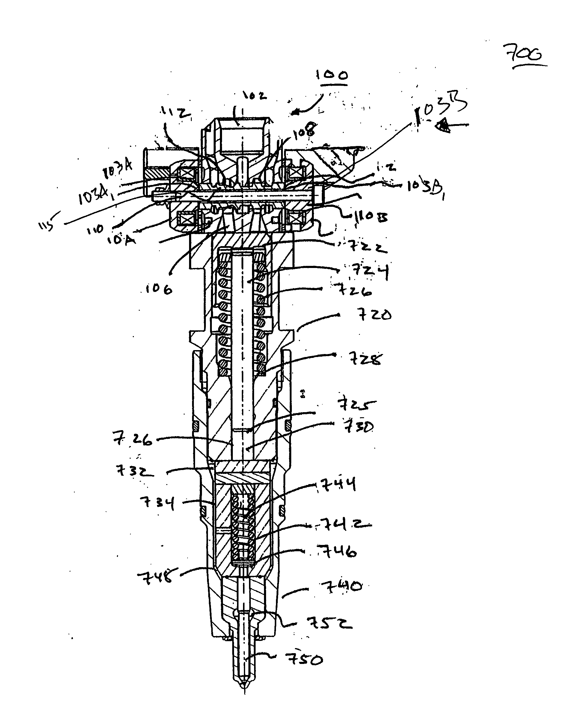
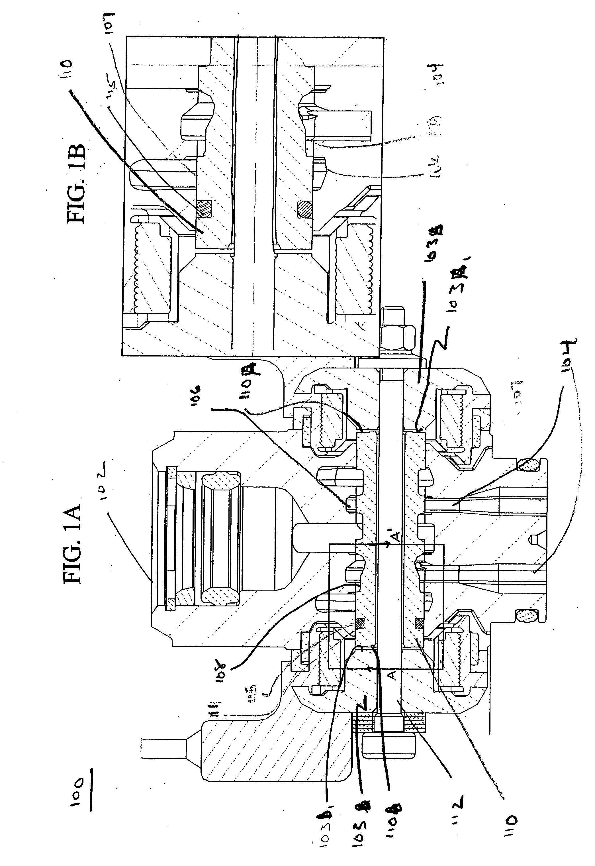
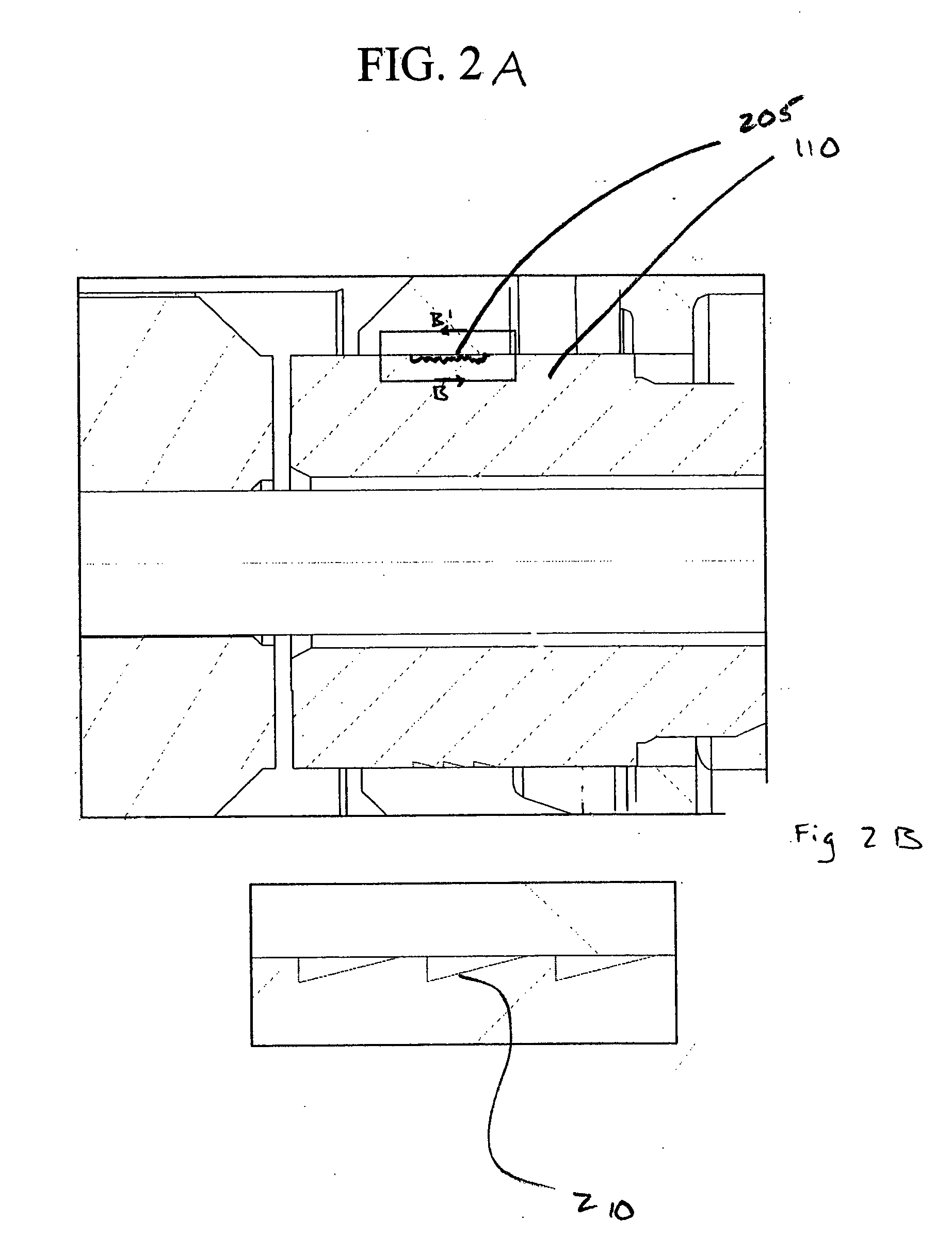
[0021] The invention is directed to a fuel injector and more particularly to a control valve assembly of the fuel injector. In the invention, latching effects, particularly hydraulic latching effects, are minimized during activation or deactivation of the open or closed solenoids of the fuel injector by removing or eliminating fluid between an end cap and spool of the control valve body. That is, the invention removes or eliminates fluid between either or both sides of the spool and the end caps of the control valve body. By removing or minimizing fluid in this area fuel decay and delayed motions of the spool can be minimized by reducing the accumulated (i.e., damned up) fluid. Although the invention eliminates, reduces or prevents the changes in hydraulic latching effects, it should be understood that the invention may equally relate to magnetic latching effects. The invention may be used as a replacement kit for a fuel injector.

Embodiments of the Oil Activated Fuel Injector of th...


PUM


Abstract

An oil activated fuel injector includes a control valve body with end cap solenoids and a slidably mounted spool. An element is arranged on a portion of the spool for minimizing latching effects of the slidably mounted spool. A drainage system may be formed in the fuel injector for reducing oil accumulation between the end cap and the control valve body. Additionally, a minimized surface area may be formed on the end of the spool or one or both of the end caps. The minimized surface area may be a raised portion of different dimensions also minimizes the latching effects.

Description

BACKGROUND OF THE INVENTION [0001] 1. Field of the Invention [0002] The present invention generally relates to a fuel injector and, more particularly, to a fuel injector that optimizes the fuel delivery and minimizes erratic injection behavior due to latching effects. [0003] 2. Background Description [0004] There are many types of fuel injectors designed to inject fuel into a combustion chamber of an engine. For example, fuel injectors may be mechanically, electrically or hydraulically controlled in order to inject fuel into the combustion chamber of the engine. In the hydraulically actuated systems, a control valve body may be provided with two, three or four way valve systems, each having grooves or orifices which allow fluid communication between working ports, high pressure ports and venting ports of the control valve body of the fuel injector and the inlet area. The working fluid is typically engine oil or other types of suitable hydraulic fluid capable of providing a pressure ...

Claims


Application Information

Patent Timeline
06 Jan 2005
Publication
US20050001055A1
IPC
F02M47/02; F02M57/02; F02M59/10; F02M59/46
CPC
F02M57/025; F02M59/466; F02M59/105
Inventors
GEBHARDT, JENS