Pedalling power generation health machine
- Summary
- Abstract
- Description
- Claims
- Application Information
AI Technical Summary
Benefits of technology
Problems solved by technology
Method used
Image

Examples
Embodiment Construction
[0001] Technical Field of the Invention
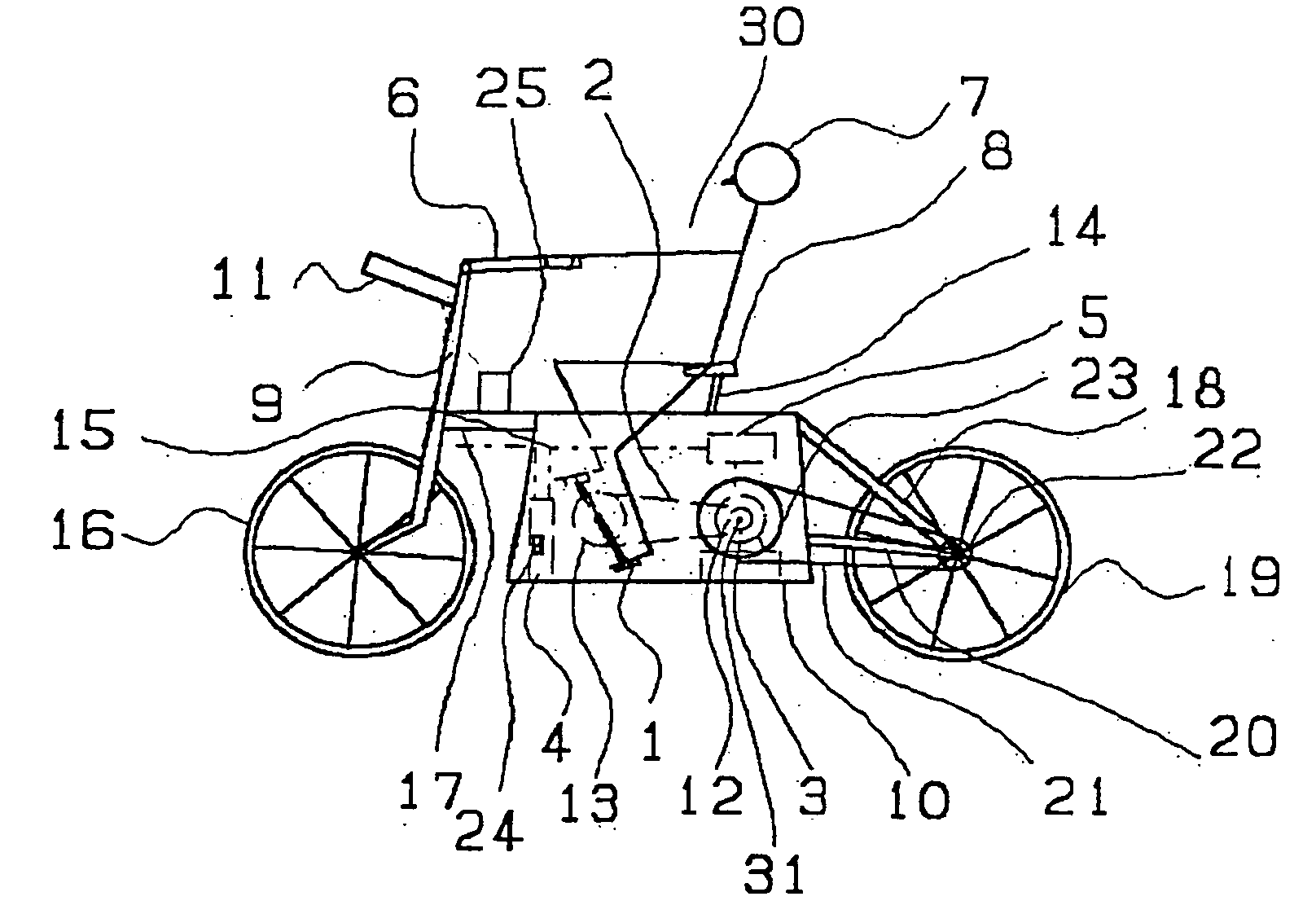
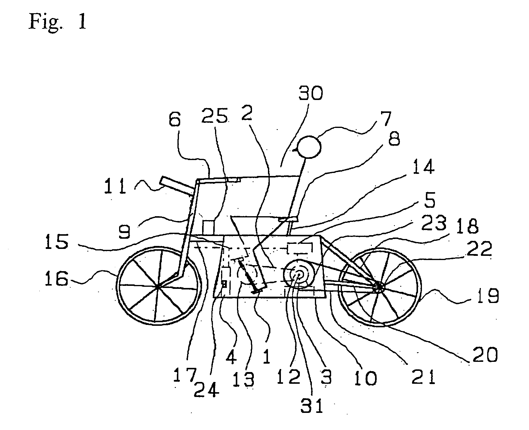
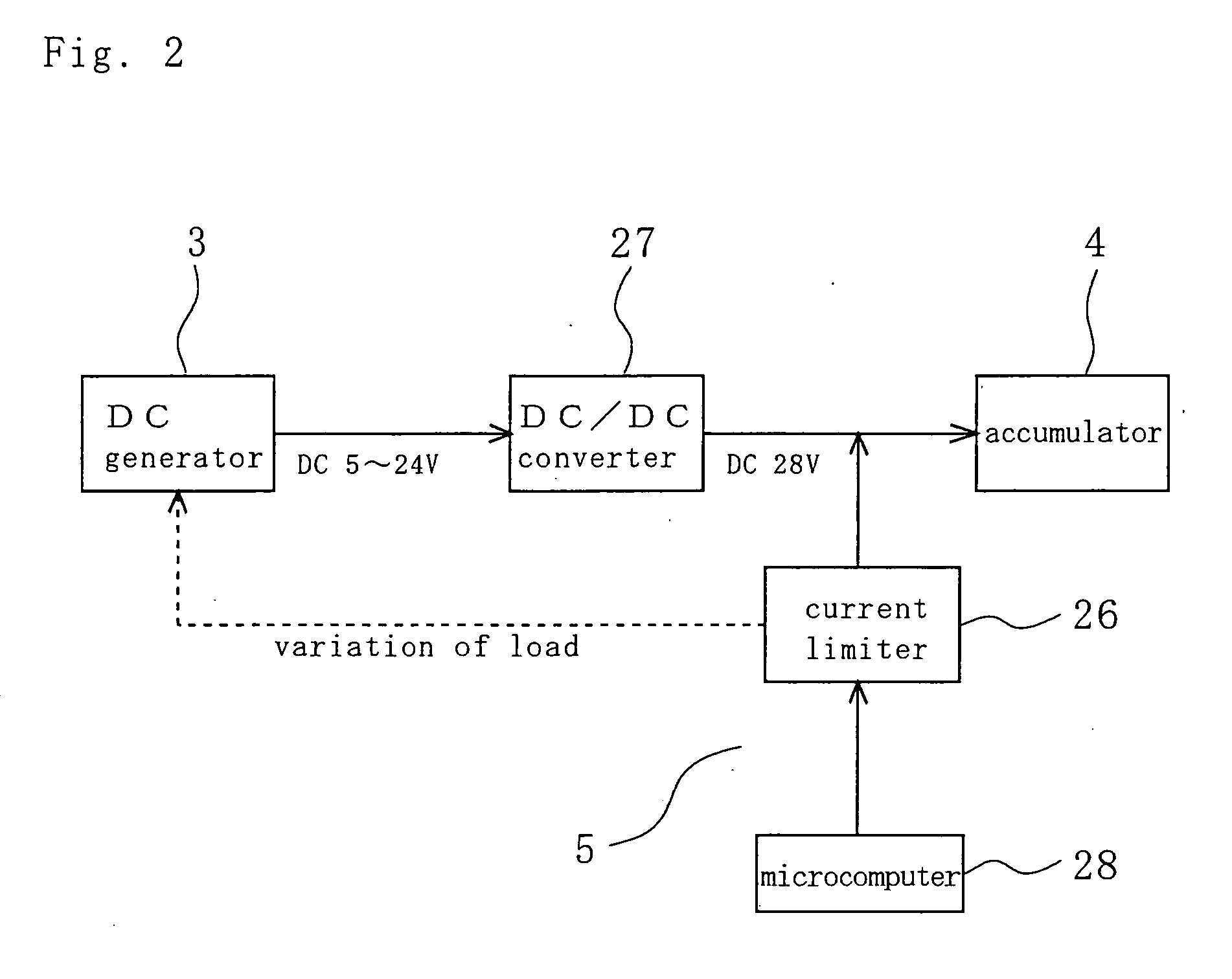
[0002] The present invention relates to an apparatus of foot pedal working type for health maintenance equipped with a generator.
BACKGROUND OF THE INVENTION
[0003] 1. Related Art
[0004] The conventional apparatus of foot pedal working type for health maintenance typically has no means for self-propelling and adapted to be always kept in stationary state for user's physical exercise. Such conventional apparatus merely displays a momentum but a kinetic energy generated by user's physical exercise is converted to a thermal energy which is uselessly released in the air.
[0005] An improved apparatus of foot pedal working type for health maintenance having a function to convert such kinetic energy to electric energy or the like and to store this converted energy is disclosed, for example, in Japanese Laid-Open Patent Application Gazette Nos. 1979-169709 and 1981-163669.
[0006] A self-propelled apparatus of foot pedal working type has been also prop...
PUM
 Abstract
Description
Claims
Application Information
 - Generate Ideas
- Intellectual Property
- Life Sciences
- Materials
- Tech Scout
- Unparalleled Data Quality
- Higher Quality Content
- 60% Fewer Hallucinations
Browse by: Latest US Patents, China's latest patents, Technical Efficacy Thesaurus, Application Domain, Technology Topic, Popular Technical Reports.
© 2025 PatSnap. All rights reserved.Legal|Privacy policy|Modern Slavery Act Transparency Statement|Sitemap|About US| Contact US: help@patsnap.com