Arterial spin labeling using time varying gradients

Inactive Publication Date: 2005-01-06
BETH ISRAEL DEACONESS MEDICAL CENT INC
View PDF7 Cites 3 Cited by
  • Summary
  • Abstract
  • Description
  • Claims
  • Application Information

AI Technical Summary

Problems solved by technology

However, magnetization transfer effects and other unrelated errors may interfere with the procedure by causing more than just the “upstream” fluid to be labeled.

Method used


Image

  • Arterial spin labeling using time varying gradients
  • Arterial spin labeling using time varying gradients
  • Arterial spin labeling using time varying gradients

Examples


Embodiment Construction

[0032] One embodiment of the present invention is described below in relation to FIGS. 2-11. Although the embodiment of FIGS. 2-11 refers to measuring perfusion of blood in the brain, the present invention is not so limited. The invention may also be applied to any MR study of fluid flow or perfusion, whether in live tissue, or under other conditions. Furthermore, the present invention may be used for angiographic studies and other medical and scientific applications, as deemed appropriate by one skilled in the art.

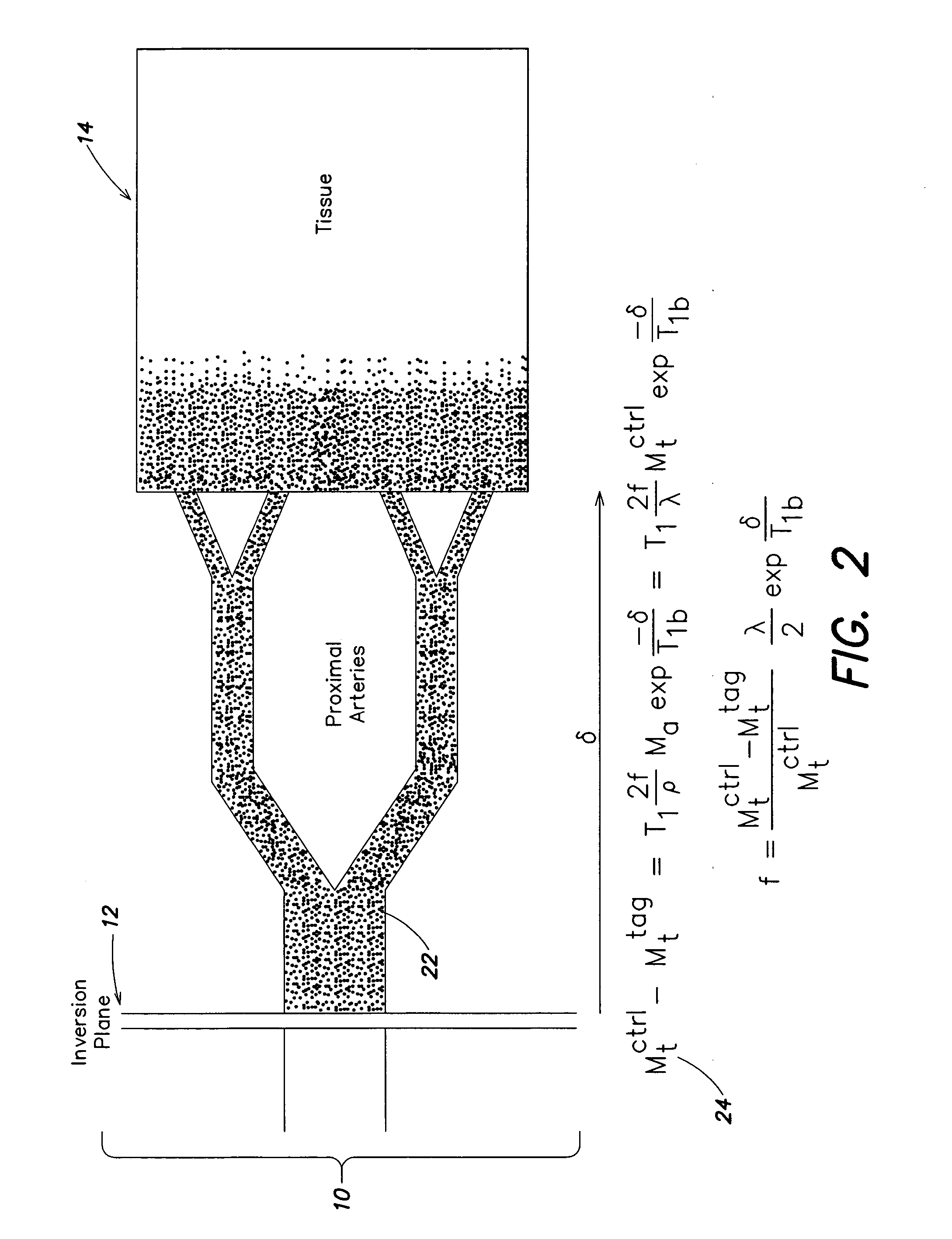
[0033] The embodiment of the invention illustrated in FIGS. 2-11 involves proton magnetic resonance imaging of perfusion using water as a freely diffusable tracer. Application of the invention to the measurement of cerebral blood flow (CBF) is detailed in relation to FIGS. 10 and 11.

[0034] Although terms “flow” and “perfusion” may sometimes be used interchangeably, perfusion as used herein refers to a diffusable exchange between a fluid and a substance, such as, for exa...


PUM


Abstract

The present invention relates to a method and system for conducting a magnetic resonance fluid flow study by conducting a labeling procedure and a control procedure and combining datasets from those procedures to create a dataset for the fluid flow study. An amplitude modulated magnetic field gradient and amplitude modulated RF irradiation may be applied during a labeling procedure. Likewise, amplitude modulated RF irradiation may be applied during a control procedure. An amplitude modulated magnetic field gradient may also be applied during the control procedure.

Description

[0001] This application is a continuation of prior application Ser. No. 10 / 121,963, filed Apr. 12, 2002, entitled ARTERIAL SPIN LABELING USING TIME VARYING GRADIENTS, which is incorporated herein by reference.FIELD OF THE INVENTION [0002] The present application relates to a technique for imaging fluid flow noninvasively using MRI with radio frequency arterial spin labeling and, more particularly, to a labeling technique that permits extension of this technique to a multi-slice or volume examination. BACKGROUND OF THE INVENTION [0003] Magnetic Resonance Imaging (MRI) is an imaging technique used primarily in medical settings to produce high quality images of the inside of the human body. MRI is based on principles of nuclear magnetic resonance (NMR), a spectroscopic technique used to obtain microscopic chemical and physical information about molecules. [0004] MR (magnetic resonance) techniques may be used to study fluid flow, such as, for example, blood flow and blood perfusion in t...

Claims


Application Information

Patent Timeline
Patent Type & Authority Applications(United States)
IPC IPC(8): G01R33/563
CPCG01R33/56366G01R33/56308
Inventor ALSOP, DAVID
Owner BETH ISRAEL DEACONESS MEDICAL CENT INC
Why Eureka
Try Eureka