

Method for providing a curved image
- Summary
- Abstract
- Description
- Claims
- Application Information
AI Technical Summary
Benefits of technology
Problems solved by technology
Method used
Image

Examples
first embodiment
[0041] Referring to FIG. 6, there is shown a first embodiment of the present invention. Image source 94 provides light from its flat source image to relay lens 54 in image generation system 70. The light output from relay lens 54 fans outward from optical axis O. A field lens 120 redirects the off-axis light through diffusing element 32 toward the center of curvature C of diffusing element 32. In contrast with the prior art approach shown in FIG. 4, the optical arrangement of FIG. 6 directs off-axis rays at a normal to the surface of diffusing element 32, minimizing the optical effects that can cause hot spots, as was described hereinabove. Moreover, by directing the light towards the center of curvature C of diffusing element 32, field lens 120 provides an optimal arrangement for using ball lens assembly 30. Referring to FIGS. 7a and 7b, there are shown the paths of light rays for both on-axis and off-axis light incident on diffusing element 32. As can be seen by comparison with th...
second embodiment
[0043] The embodiment of FIG. 6 employs conventional lens components as field lens 120. However, while there are advantages for system optical performance, the use of conventional glass or plastic optics can add bulk and weight to the overall imaging system. In response to the need to reduce size and weight, FIGS. 8, 9a, and 9b show an alternative embodiment using a curved Fresnel lens 124 and a diffusion film 126. Comparing the optical arrangement of FIG. 8 with that of FIG. 6, it can readily be seen that an embodiment using curved Fresnel lens 124 and diffusion film 126 would have advantages for reduced size and weight. FIGS. 9a and 9b show the angular spread of diffused light when using curved Fresnel lens 124 and diffusion film 126. Relative to overall performance and contrast, the conventional optics employed in the approach of FIG. 6 are slightly advantaged over the use of curved Fresnel lens 124 and diffusion film 126 in FIG. 8. However, for many applications, a slight perfor...
embodiment within
AUTOSTEREOSCOPIC SYSTEM
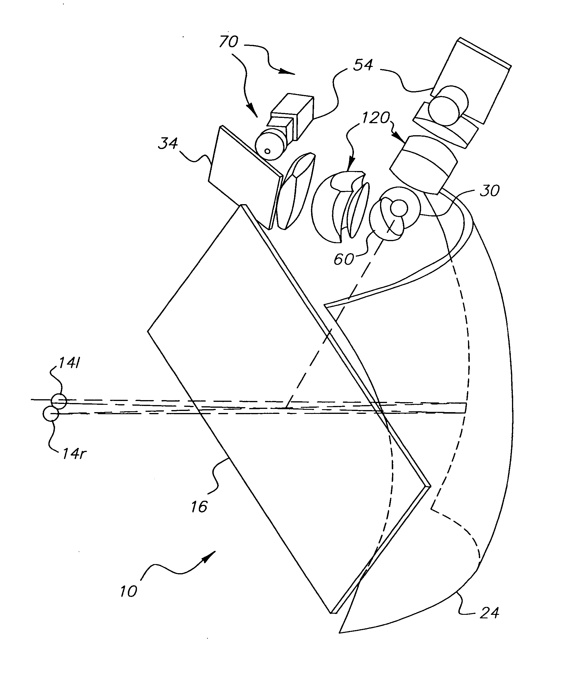
[0047] Referring to FIG. 11, there is shown a perspective view of autostereoscopic imaging apparatus 10 using image generation system 70 that employs field lens 120. For compact packaging, each image generation system 70 has a turning mirror 34 for providing modulated light from relay lens 54 to field lens 120. In the embodiment of FIG. 11, both left and right image paths employ a hemispheric lens assembly 60, as was shown in FIG. 3b.
[0048] Referring to FIG. 12, an alternate embodiment for autostereoscopic imaging apparatus 10 is shown. In this arrangement, one image generation system 70 (for left viewing pupil 14l) uses a hemispheric lens assembly 60, the other image generation 70 (for right viewing pupil 14r) employs a spherical ball lens assembly 30. By pairing these two different types of ball lenses in a single system, the arrangement of FIG. 12 offers additional opportunities for compact packaging of autostereoscopic imaging apparatus 10.
[0049] The inv...
PUM
 Abstract
Description
Claims
Application Information