
Method and apparatus for tracking maximum power point for inverters, for example, in photovoltaic applications

a technology of inverter and maximum power point, which is applied in the direction of electric variable regulation, process and machine control, instruments, etc., can solve the problems of photovoltaic energy generation difficulties, iv droop characteristics of photovoltaic cells, and relatively low energy density (efficiency) of photovoltaic cells

Active Publication Date: 2005-01-06
RHOMBUS ENERGY SOLUTIONS
View PDF21 Cites 258 Cited by
  • Summary
  • Abstract
  • Description
  • Claims
  • Application Information

AI Technical Summary

Problems solved by technology

However, there are difficulties encountered with photovoltaic energy generation which are not present in conventional energy generation systems.
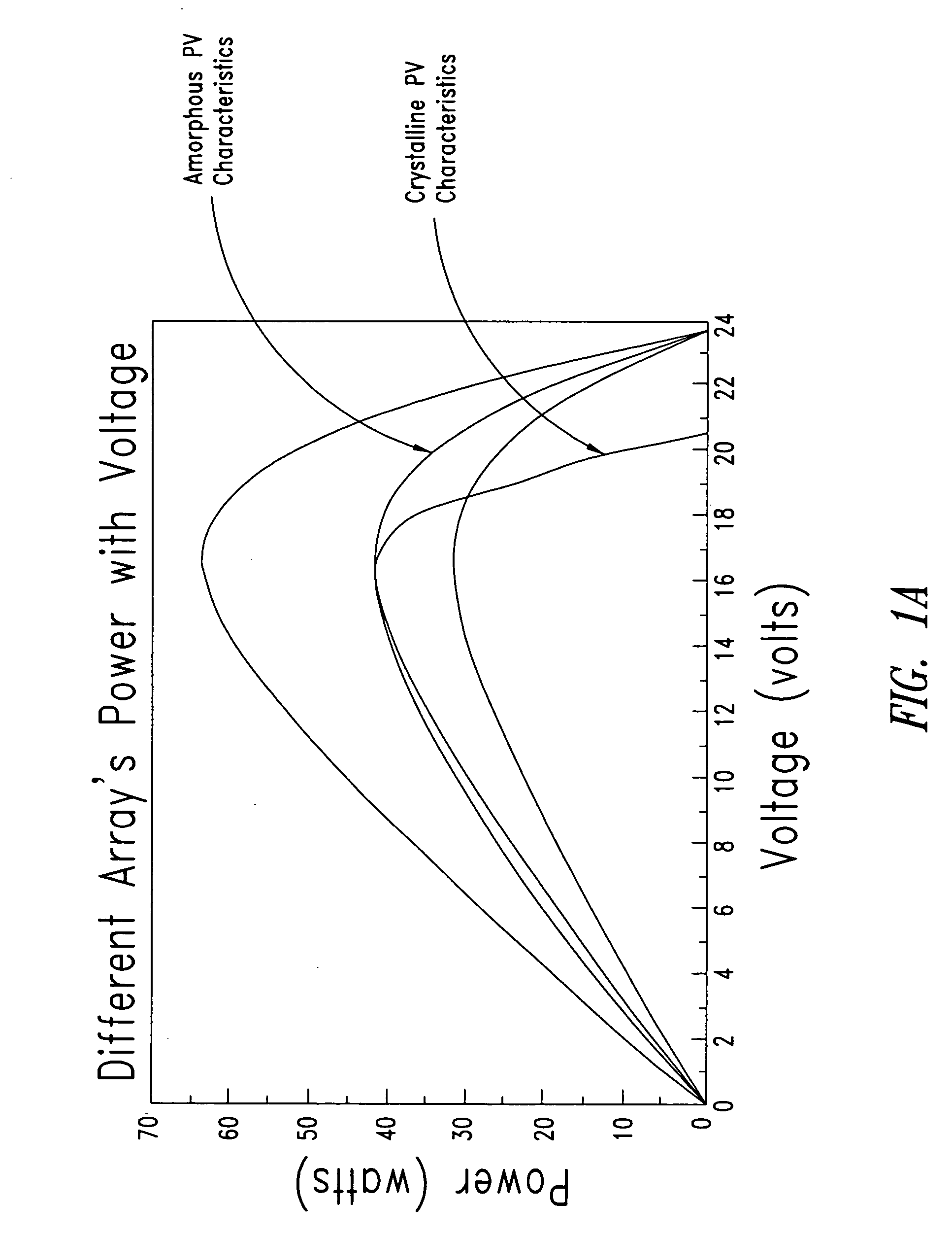
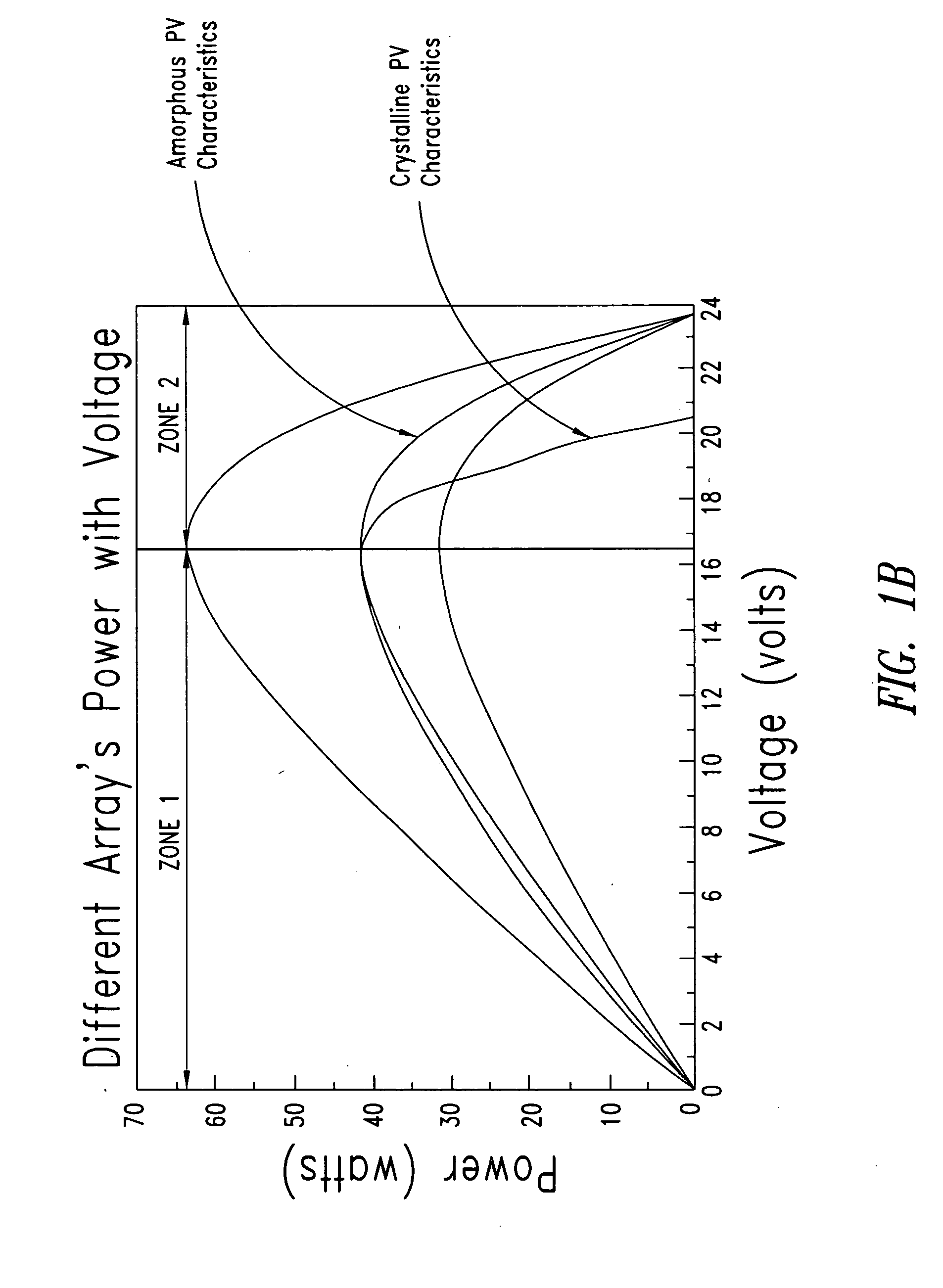
These issues include the peculiar IV droop characteristics of photovoltaic cells, the cost, and the relatively low energy density (efficiency) of photovoltaic cells.
Photovoltaic cells are still relatively expensive and it's energy conversion efficiency is still relatively low so a wide area is required to generate sizable power.
Although this technique attempts to track the MPP without explicitly computing the voltage-current product for the panel power, the curve-fitting technique cannot predict many characteristics including other complex factors, such as aging, temperature, and a possible breakdown of individual cells.
This requires a very slow filter in the power calculation and voltage measurements which may detrimentally limit the response time.
Thus, a rapid change in isolation level may cause problems in systems employing such techniques.
Consequently, such an approach is not cost effective.

Method used


Image

  • Method and apparatus for tracking maximum power point for inverters, for example, in photovoltaic applications
  • Method and apparatus for tracking maximum power point for inverters, for example, in photovoltaic applications
  • Method and apparatus for tracking maximum power point for inverters, for example, in photovoltaic applications

Examples


Embodiment Construction

[0026] In the following description, certain specific details are set forth in order to provide a thorough understanding of the various embodiments of the invention. However, one skilled in the art will understand that the invention may be practiced without these details. In other instances, well-known structures associated with photovoltaic arrays, inverters and processors or controllers have not been shown or described in detail to avoid unnecessarily obscuring descriptions of the embodiments.

[0027] Unless the context requires otherwise, throughout the specification and claims which follow, the word “comprise” and variations thereof, such as, “comprises” and “comprising” are to be construed in an open, inclusive sense, that is as “including, but not limited to.”

[0028] Reference throughout this specification to “one embodiment” or “an embodiment” means that a particular feature, structure or characteristic described in connection with the embodiment is included in at least one emb...


PUM


Abstract

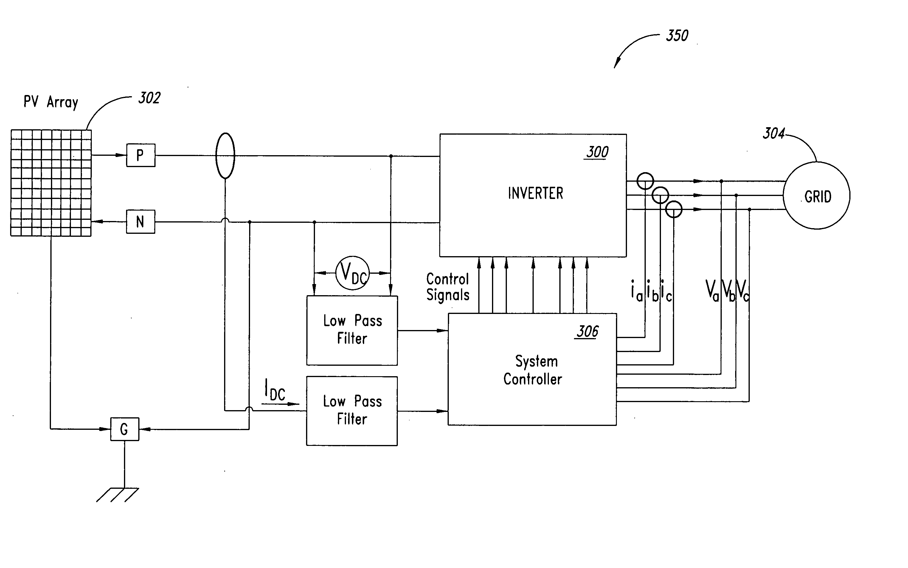
A power system employs an outer voltage feedback loop and an inner current feedback loop to control a power converter, such as a DC to AC inverter for transferring electrical power between a power source, for example a photovoltaic array, and a load, for example a power grid. The outer loop accommodates variations in the output of the power source, for example accommodating anomalies in IV characteristics such as IV droop characteristic associated with photovoltaic cells. The outer loop may employ a first control regime or a second control regime, for example, dependent on whether a DC bus voltage or power is smaller than a value corresponding to measurement resolution or expected noise.

Description

BACKGROUND OF THE INVENTION [0001] 1. Field of the Invention [0002] This disclosure is generally related to power inverters, and particularly to inverters that invert power from photovoltaic sources. [0003] 2. Description of the Related Art [0004] A photovoltaic cell is one of the cleanest and environment-friendly non-conventional energy sources. A photovoltaic cell directly converts solar energy into electrical energy. The electrical energy produced by the photovoltaic cell can be extracted over time and used in the form of electric power. This electric power can be used to drive electric devices. Typically the power is extracted by use of DC-DC up / down converter circuitry and / or DC / AC inverter circuitry. [0005] The popularity of photovoltaic energy generation is rapidly increasing worldwide. One reason for such popularity is that the energy produced by photovoltaic energy generation is essentially pollution free, unlike conventional energy sources such as fossil fuel burning therm...

Claims


Application Information

Patent Timeline
Patent Type & Authority Applications(United States)
IPC IPC(8): G05F1/67
CPCY02E10/58G05F1/67Y02E10/56
Inventor DENG, DUOTULADHAR, ANILFARKAS, KENNETH J.GRAND, KERRY E.
Owner RHOMBUS ENERGY SOLUTIONS
Learn More