Write signal control circuit in an optical disk drive
a control circuit and optical disk technology, applied in the direction of digital signal error detection/correction, instruments, recording signal processing, etc., can solve the problems of data error, buffers, and the output drive within the write signal generator also become more serious, so as to avoid the improper duty cycle of write signals
- Summary
- Abstract
- Description
- Claims
- Application Information
AI Technical Summary
Benefits of technology
Problems solved by technology
Method used
Image
Examples
Embodiment Construction
[0025] The write signal control circuit in an optical disk drive of the present invention will be described with reference to the accompanying drawings.
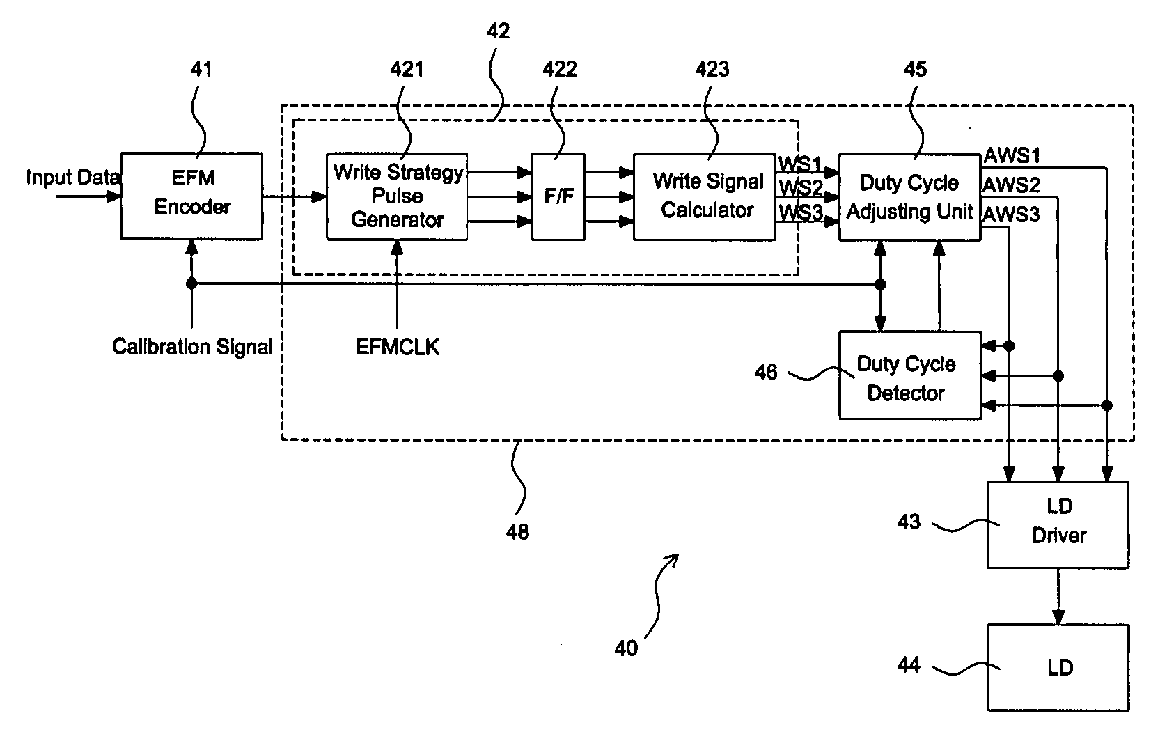
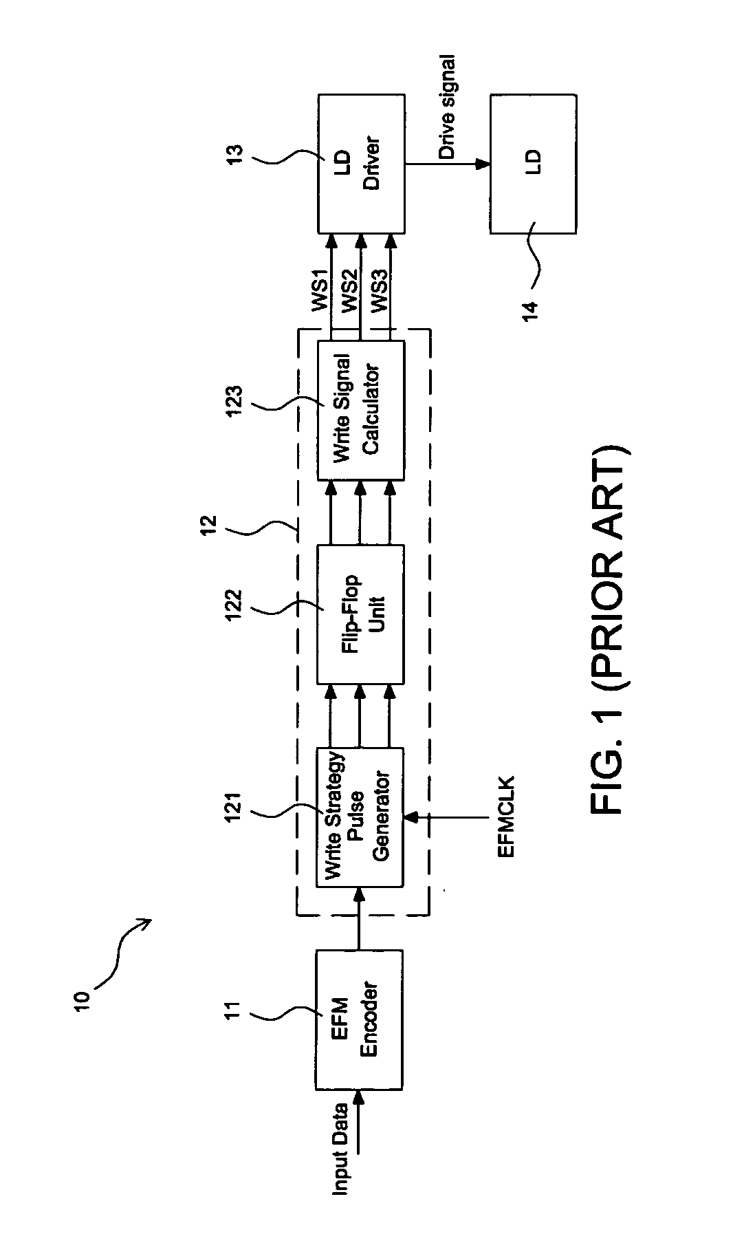
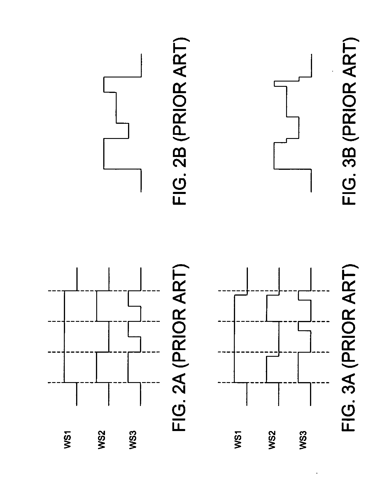
[0026] In the typical laser power control system, the write signals outputted from the typical write signal generator are directly outputted to the LD driver without being further detected whether the duty cycles of the write signals are proper or not. However, a practical laser power control system usually suffer from the problem of duty cycle distortion of the write signals induced by the practical implementations of the digital logic gate, the buffers, and the output drive unit. In order to solve the problems, the present invention utilizes a duty cycle detector to detect the duty cycles of the write signals, and a duty cycle adjusting unit to adjust the duty cycles of the write signals, such that the duty cycles of the write signals outputted to the LD driver are proper in the sense that the duty cycle distortion is minimized.
[...
PUM
 Abstract
Description
Claims
Application Information
 - R&D
- Intellectual Property
- Life Sciences
- Materials
- Tech Scout
- Unparalleled Data Quality
- Higher Quality Content
- 60% Fewer Hallucinations
Browse by: Latest US Patents, China's latest patents, Technical Efficacy Thesaurus, Application Domain, Technology Topic, Popular Technical Reports.
© 2025 PatSnap. All rights reserved.Legal|Privacy policy|Modern Slavery Act Transparency Statement|Sitemap|About US| Contact US: help@patsnap.com


