Probe for a body cavity

Inactive Publication Date: 2005-01-06
FRADEN JACOB
View PDF20 Cites 27 Cited by
  • Summary
  • Abstract
  • Description
  • Claims
  • Application Information

AI Technical Summary

Benefits of technology

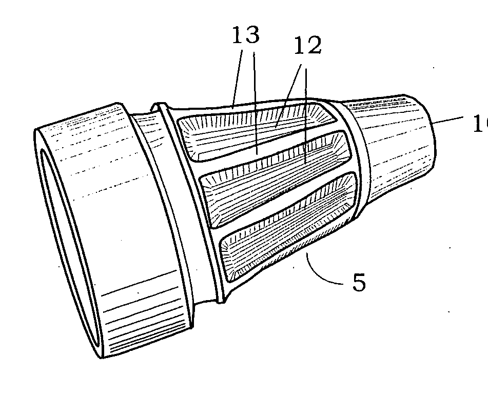
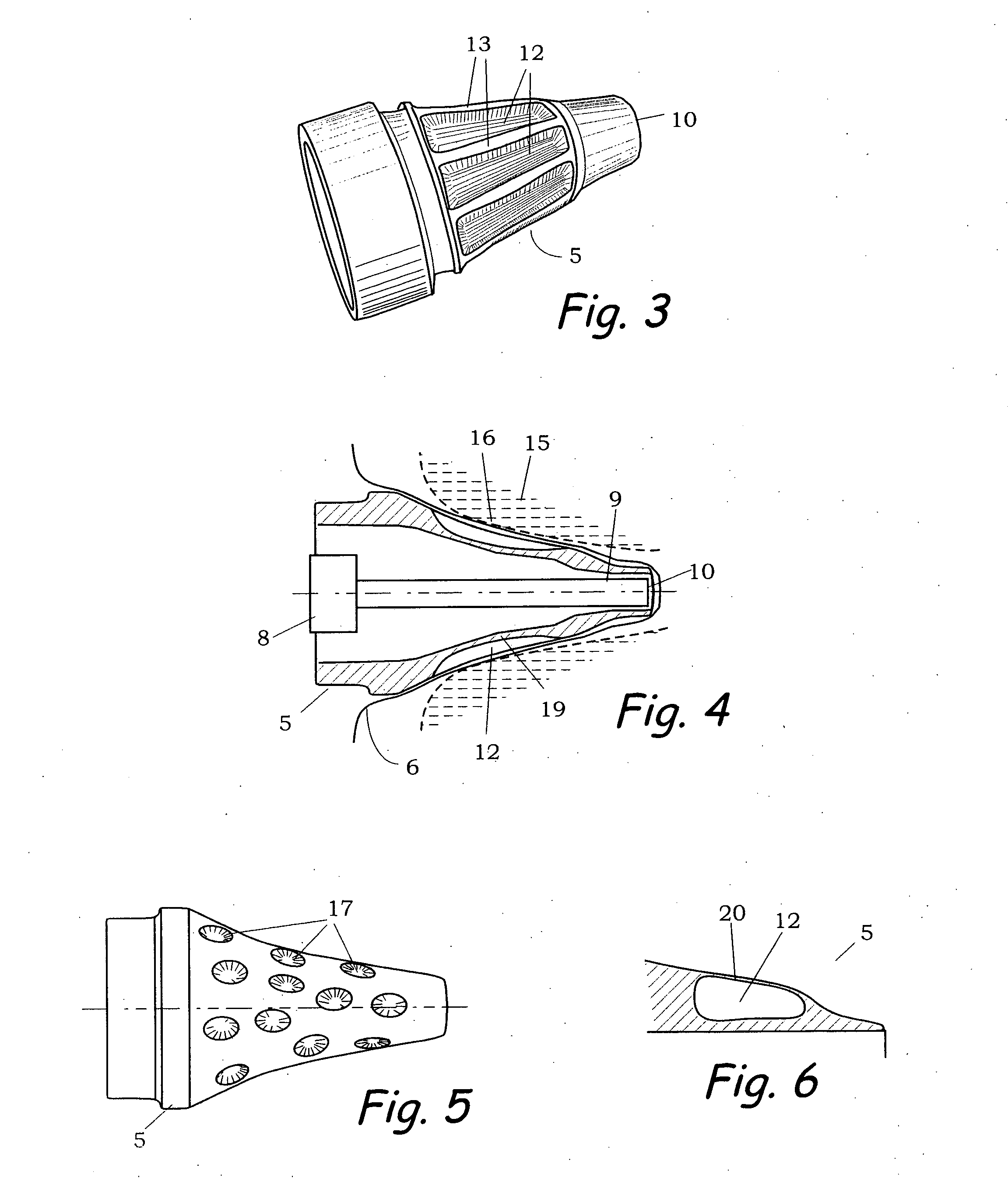
[0010] A medical probe for collecting signals from a body cavity having a profile which is combination of an outside frustum shape and the multiple surface cavities or indentations situated on the probe outer surf

Problems solved by technology

Temperature of the walls may adversely affect performance of such components.
Transmission of heat through the side walls of the probe may be a source of large errors since the IR sensor can't distinguish between heat received in the IR form and that r

Method used


Image

  • Probe for a body cavity
  • Probe for a body cavity
  • Probe for a body cavity

Examples


Example

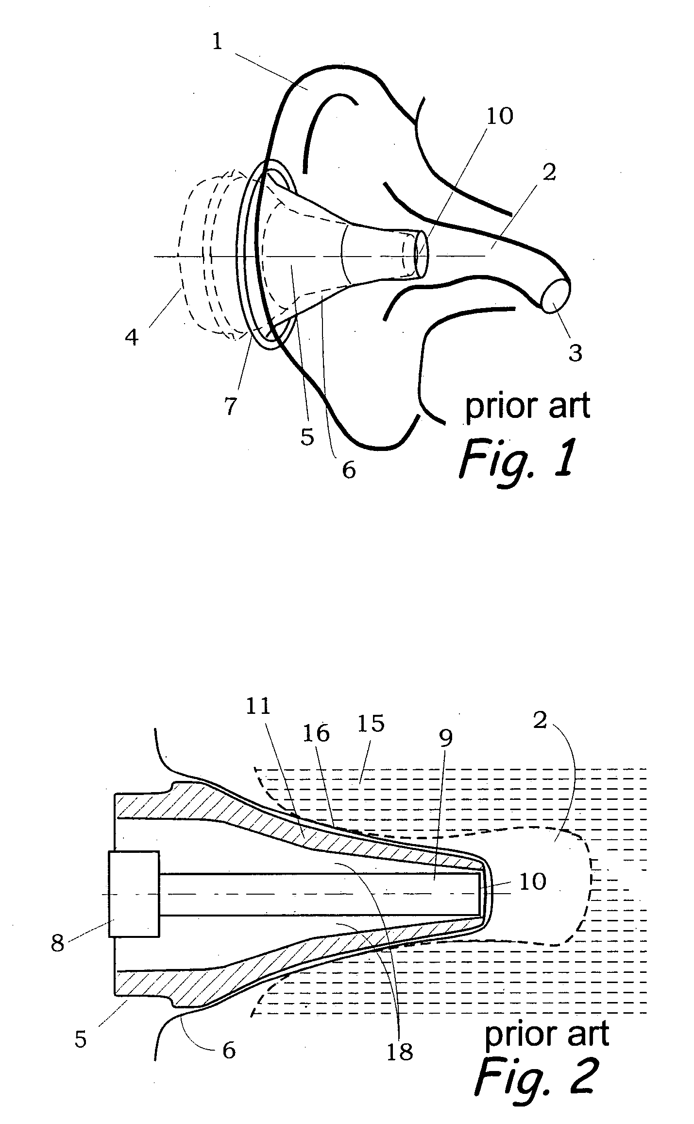
[0017] The present invention describes a probe for insertion into a body cavity, such as an ear canal, rectum, mouth and other that may be used for collecting medical signals. However, below we describe a specific probe for of an instant ear thermometer as an example of the most typical application. The probe has a reduced heat transfer through it side walls and thus substantially minimizes effects of the lateral heat transfer through the probe walls. Such a probe may be fabricated of such resins as ABS, nylon, and other plastics having a continuous or foamy structures that may further reduce thermal conductivity. Glass or ceramics also may be employed for fabricating the probe. By way of comparison with prior art, FIG. 1 shows a conventional prior art probe 5 that is attached to the infrared (IR) ear thermometer 4 which is shown here only partially. Probe 5 is covered with probe cover 6 having attachment ring 7. The probe cover is a thin plastic sheath. The assembly is inserted int...


PUM


Abstract

A medical probe for collecting signals from a body cavity having a profile which is a combination of an outside frustum shape and the multiple surface cavities or indentations situated on the probe outer surface. The probe outer surface when enveloped by a thin probe cover material forms air pockets, thus reducing thermal conductivity across the probe walls and minimizing negative effects of the lateral heat transfer.

Description

FIELD OF INVENTION [0001] This invention relates to devices for measuring signals from a body cavity, more specifically to infrared noncontact ear thermometers, primarily intended for medical and veterinary applications. DESCRIPTION OF PRIOR ART [0002] There are the information collecting probes of medical instruments intended for insertion into an orifice of a body of a human or animal. The probes may contain components that are sensitive to temperature of the cavity walls. Temperature of the walls may adversely affect performance of such components. An example of an instrument is an infrared (IR) thermometer which is a device capable of measuring temperature without a physical contact with the object of measurement. The measurement is done by detecting intensity of the IR radiation which is naturally emanated from the object's surface. For objects having temperatures in the range between 0 and 100° C., this requires use of sensors for detecting IR radiation in the wavelength from ...

Claims


Application Information

Patent Timeline
IPC IPC(8): G01J5/02G01K1/08
CPCG01J5/049G01J5/04
Inventor FRADEN, JACOB
Owner FRADEN JACOB
Why Eureka
Try Eureka