

Refrigerant compressor
a compressor and refrigerant technology, applied in the direction of pump components, positive displacement liquid engines, liquid fuel engine components, etc., can solve the problems of increasing the manufacturing cost of the muffler insignificantly or not at all, achieving partly substantial noise muffling, and improving thermal isolation. , the effect of excellent isolation
- Summary
- Abstract
- Description
- Claims
- Application Information
AI Technical Summary
Benefits of technology
Problems solved by technology
Method used
Image

Examples
Embodiment Construction
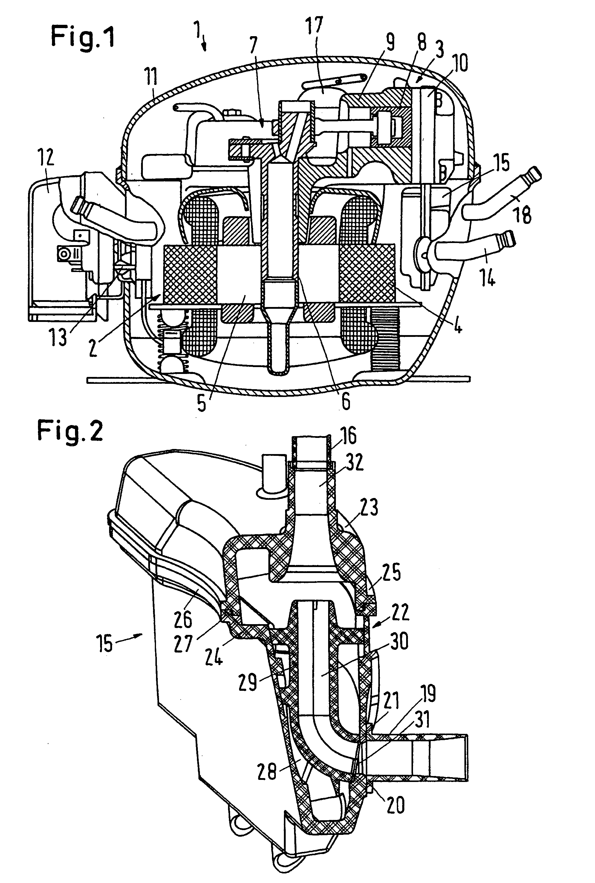
[0019]FIG. 1 shows a refrigerant compressor 1 with a motor 2, which drives a compressor 3. The motor 2 has a stator 4 and a rotor 5. The rotor 5 is connected with a shaft 6, which drives a piston 8 in a cylinder 9 via a crankshaft drive 7. The cylinder 9 is closed by a cylinder head 10, in which, in a manner known per se, valves are located, which control the filling of a compression chamber in the cylinder 9 with refrigerant gas, or the discharge of the refrigerant gas from the compression chamber, respectively.
[0020] The parts mentioned are enclosed in a case 11, which encloses the motor 2 and the compressor 3 hermetically. The outside of the case is provided with an electronic connection device 12, if required with a control, which controls the operation of the motor 2 in dependence of predetermined values, for example the refrigeration requirement of a refrigerator, not shown in detail. The device 12 is connected with the motor 2 via lines 13 guided through the case.
[0021] Ref...
PUM
 Abstract
Description
Claims
Application Information