
Fuel cell system and method to operate a fuel cell system

Inactive Publication Date: 2005-01-06
NUCELLSYS
View PDF7 Cites 2 Cited by
  • Summary
  • Abstract
  • Description
  • Claims
  • Application Information

AI Technical Summary

Benefits of technology

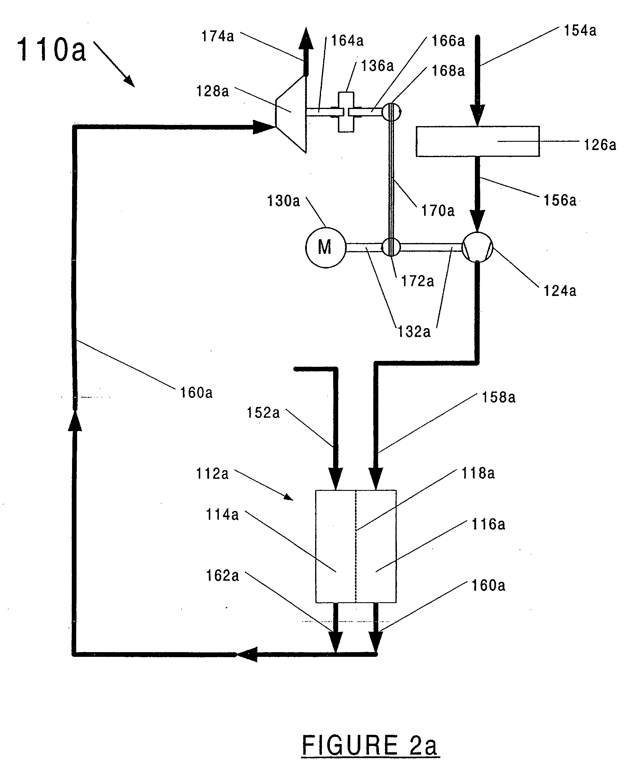
[0009] In brief, the present invention is directed to a fuel cell system with lower hardware and design complexity in which the cathode compressor and the expansion device can be coupled on demand in order to increase efficiency.

Problems solved by technology

However, the implementation of the fuel cell system according to this prior art requires a relatively high hardware complexity.
In operating states in which the expansion of the exhaust gases taking place in the expansion device can not generate sufficient mechanical energy to power the cathode compressor—together with the cathode compressor's motor drive—, the expansion device will be dragged by the motor drive of the cathode compressor.
This reduces the efficiency of the fuel cell system.
This solution is complex with respect to the measurement technology required and additionally requires a control for the electromagnetic clutch.
However, because the drive shaft extends out of the motor drive on both sides, this solution is comparatively bulky and requires a large amount of space.
Moreover, the long motor shaft increases the mass moment of inertia of the system and reduces the efficiency of the system.

Method used


Image

  • Fuel cell system and method to operate a fuel cell system
  • Fuel cell system and method to operate a fuel cell system
  • Fuel cell system and method to operate a fuel cell system

Examples


Embodiment Construction

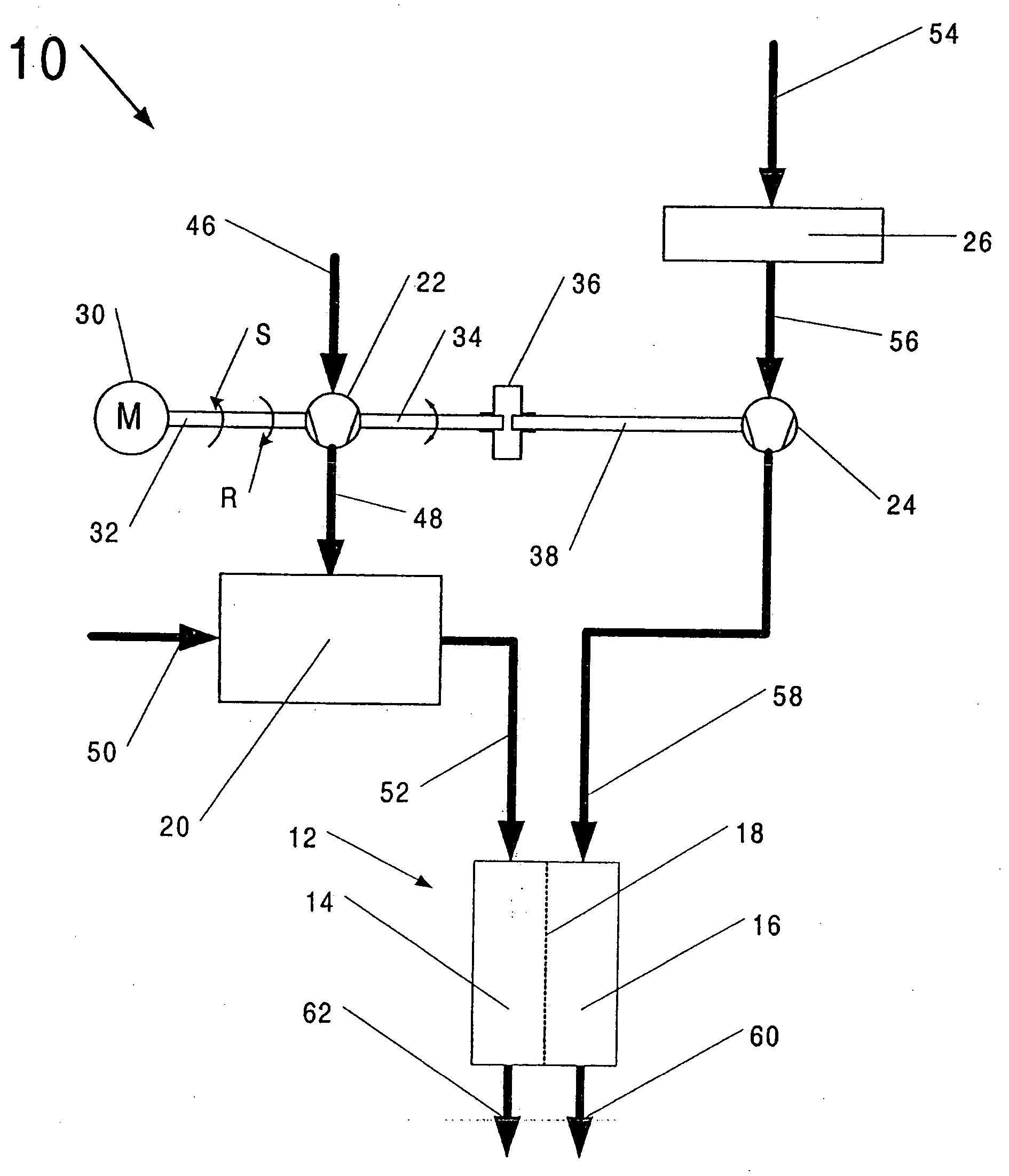
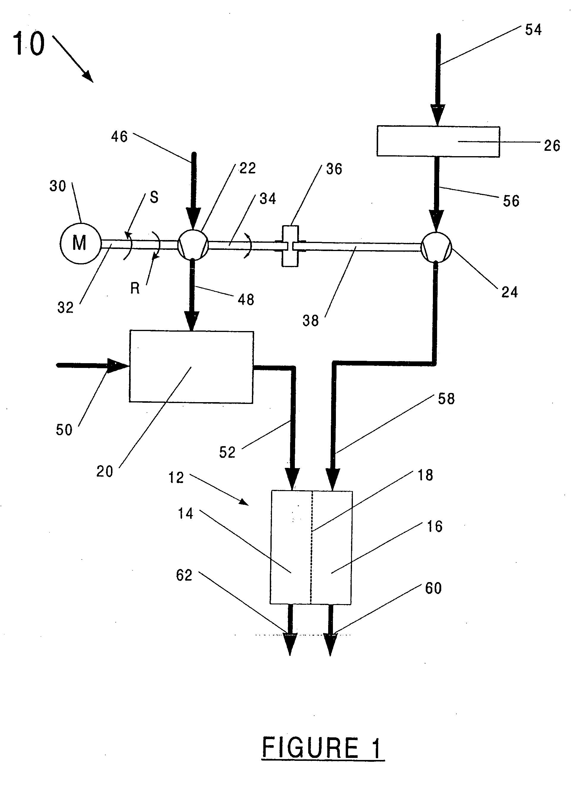
[0038] In FIG. 1, the entirety of a first embodiment example of a fuel cell system according to the invention is labeled 10. It comprises fuel cell 12, which is operated in a manner known in the art to generate power from a fuel gas, e.g., hydrogen, and an oxidant, e.g., oxygen, which is obtained from supplied ambient air. The fuel cell is a PEM fuel cell (PEM: Proton Exchange Membrane), i.e., a fuel cell with a proton exchange membrane. The fuel cell 12 possesses an anode side 14 and a cathode side 16, which are separated by the proton exchange membrane 18.

[0039] The fuel cell system 10 further comprises reformer 20, which is arranged on the anode side and generates a fuel gas from a starting gas, e.g., a hydrocarbon. A compressor 22 is connected upstream of the reformer 20, whereby the compressor—due to being associated with the anode side 14 of the fuel cell 12—hereafter will be referred to as the anode compressor 22.

[0040] The fuel cell system 10 is also equipped with a compre...


PUM


Abstract

A fuel cell system comprising a fuel cell which contains an anode and a cathode, further comprising a cathode compressor to supply process air to the fuel cell, and an anode compressor to supply fuel gas to the fuel cell, whereby the cathode compressor and the anode compressor can be driven by a common motor drive, and whereby an automatic clutch is provided to couple and decouple the driving of the cathode compressor and the anode compressor.

Description

CROSS-REFERENCE TO RELATED APPLICATIONS [0001] This application claims the benefit of U.S. Provisional Patent Application No. 60 / 529,418 filed Dec. 12, 2003, and also claims priority to German Application No. 103 12 647.3 filed Mar. 21, 2003, both of which applications are incorporated herein by reference in their entireties.BACKGROUND OF THE INVENTION [0002] 1. Field of the Invention [0003] The invention relates to a fuel cell system comprising a fuel cell, which contains one cathode and one anode, further comprising one cathode compressor to supply process air to the fuel cell, and one expansion device in an exhaust gas line issuing from the fuel cell, whereby the cathode compressor is drivable by an electric motor drive and whereby the expansion device is or can be coupled for driving purposes to the cathode compressor via an automatic clutch. [0004] 2. Description of the Related Art [0005] Fuel cell systems are known in the prior art. For example, DE 199 51 584 A1 is directed to...

Claims


Application Information

Patent Timeline
IPC IPC(8): H01M8/04H01M8/06H01M8/10
CPCH01M8/04089H01M8/04111Y02E60/50H01M8/0612H01M8/1002H01M8/04268H01M8/1007
Inventor SANG, JOCHENKNOOP, ANDREASBERG, FALKO
Owner NUCELLSYS
Learn More