Magnetically navigable and/or controllable device for removing material from body lumens and cavities

a technology of lumen and cavity, which is applied in the field of magical navigability and/or controllable devices for removing material from body lumens and cavities, can solve the problems of difficult to accurately control the atherectomy device satisfactorily, require great skill, and slow and tedious process of navigating guide wire through blood vessels, etc., to facilitate the navigation of the atherectomy device, facilitate orientation and/or movement of the guide wire, and facilitate the effect of guiding

Inactive Publication Date: 2005-01-06
HALL ANDREW F +3
View PDF8 Cites 202 Cited by
  • Summary
  • Abstract
  • Description
  • Claims
  • Application Information

AI Technical Summary

Benefits of technology

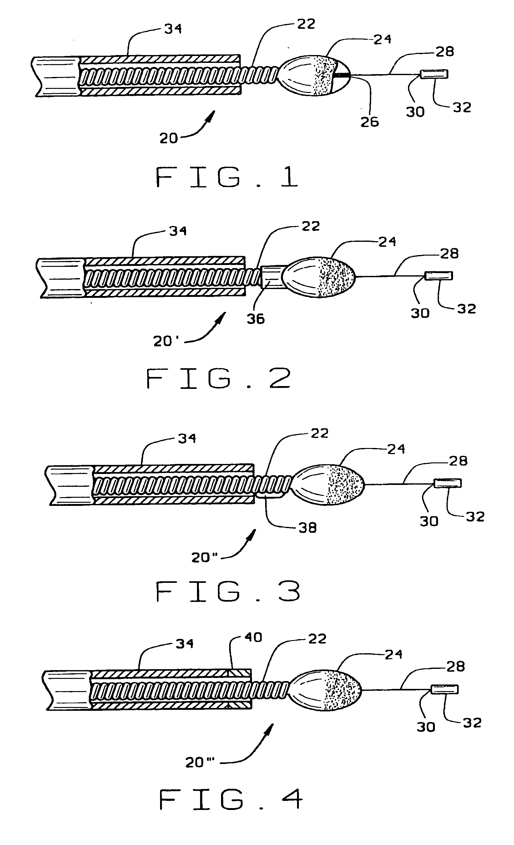
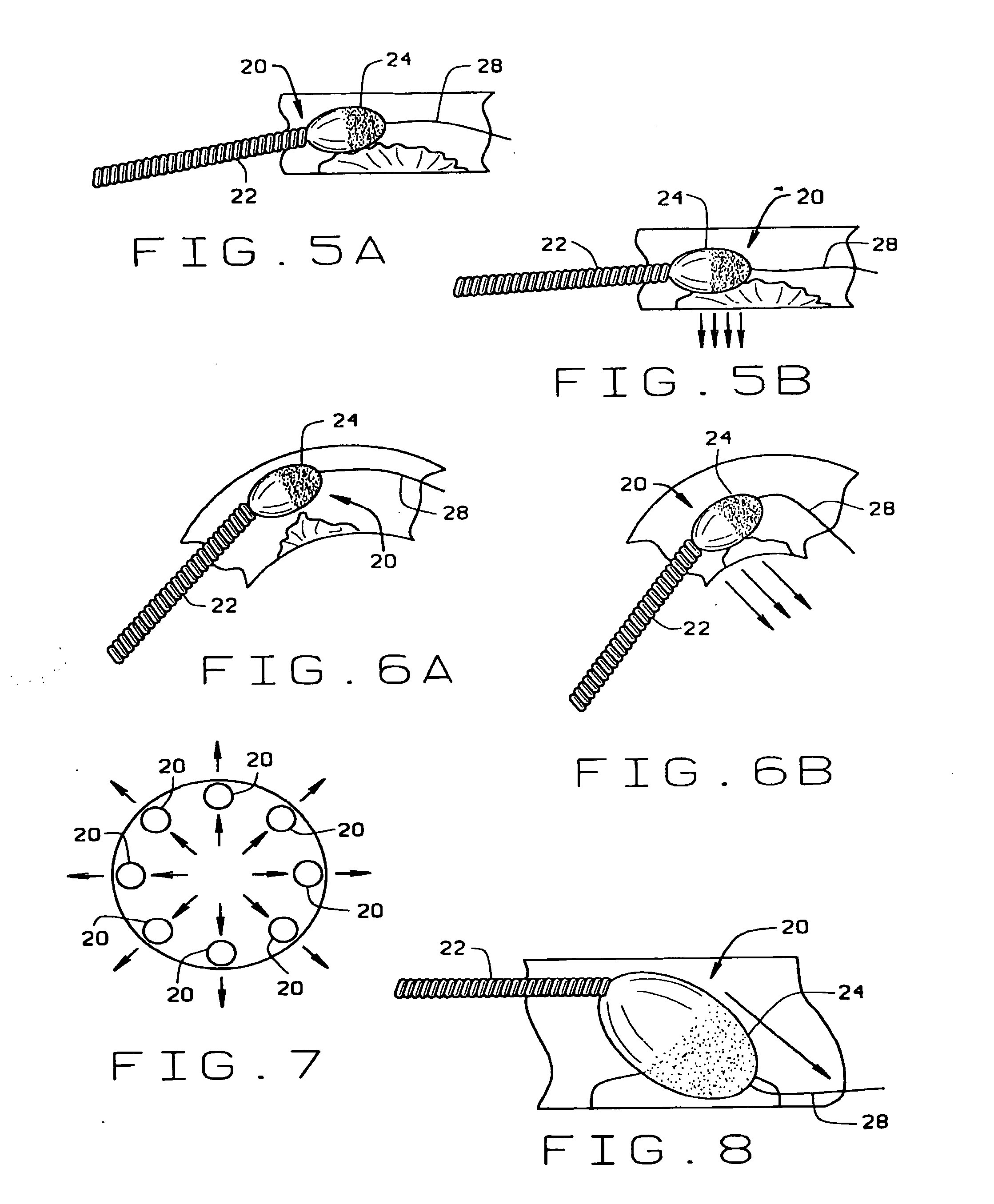
[0005] The magnet associated with the cutting head facilitates navigation of the atherectomy device to the procedure site, and control of the cutting head at the procedure site through the application of a magnetic field and / or magnetic field gradient. A magnetic field can be applied to orient the atherectomy device in the blood vessel for navigating to the procedure site. The applied magnetic field aligns the magnet associated with cutting head in the direction of the field, so that the atherectomy device can be more easily steered through the blood vessels. The device can then be advanced in the desired direction simply by pushing on the proximal end. Alternatively, or in addition, a magnetic field gradient can be applied to the magnet associated with the cutting head to apply force to the atherectomy device to actually move the device through the blood vessel, or assist the mechanical pushing of the device through the blood vessel. Once at the procedure site, magnetic fields and / or magnetic field gradients can be applied to the magnet associated with the cutting head to control the orientation of the device and its position within the cross-section of the blood vessel. Thus, with the application of a magnetic field, the cutting portion of the cutting head can be oriented toward the accumulated atheromatous material, and the cutting tool itself can be moved within the cross-section of the blood vessel to act on the accumulated atheromatous material, for example on the insides of bends. Because the tool can be both oriented and moved, the tool can open a passage in the blood vessel that is larger than the cross section of the device itself. By automating the control of the direction and / or gradient of the applied magnetic field, the procedure can be automated, so that once the tool is navigated to the site of the disease, the tool is automatically precessed to clear the cross-section of the vessel in adjacent the atherectomy device of the atheromatous material. In addition to precessing the cutting head by continuously changing the magnetic field, it is also possible to continuously move the cutting head around the cross-section of the vessel by continuously varying the magnetic gradient. Of course both the magnetic field and magnetic gradient can be simultaneously changed to cause the orientation and the position of the cutting head to change to remove material from around the cross section of the vessel.
[0006] In accordance with another embodiment of this invention, it is also possible that instead of, or in addition to, associating a magnet with the cutting head, the atherectomy device can be used in conjunction with a magnetic guide wire. A magnet can be provided on the end of a conventional guide wire, or a portion of the guide wire can be made magnetic. The guide wire is then navigated to the diseased site. The magnet on or in the guide wire facilitates orienting and / or moving the guide wire through the blood vessels. Once at the site, the atherectomy device can be brought into close association with the magnet on the guide wire, and the magnet on the guide wire can be used to orient and to move the cutting head within the blood vessel.
[0007] The atherectomy device of the present invention can be quickly and easily navigated to the site of the disease. This makes the procedure easier on the physician and the on patient. Once at the site, the tool can be operated more effectively, removing atheramotous material from around the entire circumference of the blood vessel, and clearing a passageway larger than the cross section of the atherectomy device itself. These and other features and advantages will be in part apparent and in part pointed out hereinafter.

Problems solved by technology

The navigation of the guide wire through the blood vessel can be a slow and tedious process, requiring great skill.
Once at the site of the disease, it can be difficult to precisely control the atherectomy device to satisfactorily remove the atheromatous material.
Part of this difficulty arises from guide wire bias, for example as the atherectomy device traverses bends in the blood vessels the guide wire and device tend to move toward the outside of the bend, making it difficult to remove atheromatous material from the insides of the bends.
Even in straighter segments of blood vessels, it is difficult to control the position of the atherectomy device within the cross section of the blood vessel, or the orientation of the cutting head of the atherectomy device within the blood vessel, and thus it is difficult to form a passage through the vessel larger than that cross section of the tool.

Method used


Image

  • Magnetically navigable and/or controllable device for removing material from body lumens and cavities
  • Magnetically navigable and/or controllable device for removing material from body lumens and cavities
  • Magnetically navigable and/or controllable device for removing material from body lumens and cavities

Examples


second embodiment

[0030] In accordance with this invention, shown in FIG. 9A and 9B, it is also possible that instead of, or in addition to, associating a magnetic with the cutting head, the atherectomy device can be used in conjunction with a magnetic guide wire 100, having a magnetic distal end portion. As shown in FIG. 9A, the guide wire 100 has a discrete magnet 102 on its distal end. As shown in FIG. 9B, the distal end portion 104 of the guide wire 100 is made from a magnetic wire material. The guide wire is then navigated to the diseased site. The magnet on or in the guide wire facilitate orienting and / or moving the guide wire through the blood vessels. Once at the site, the atherectomy device can be brought into close association with the magnet on the guide wire, and the magnet on the guide wire can be used to orient and to move the cutting head within the blood vessel.

third embodiment

[0031] In accordance with this invention, shown in FIG. 10, the atherectomy device can be used without any guide wire. The device is navigated solely by the application of magnetic fields and / or gradients, which apply a force through the magnet associated with the cutting head. One method of navigating such an atherectomy device is that disclosed in co-assigned U.S. patent application Ser. No. 60 / 095,710 filed Aug. 7, 1998, and incorporated herein by reference. In this method of navigation, the operating region in the patient is viewed on two planar fluoroscopic images of the operating region. The physician identifies the current position of the atherectomy device on each display, for example by using a mouse or similar device to point and click on the desired location. Similarly the physician can identify the desired new position of the atherectomy device on each display. A computer can control an electromagnetic system for generating an electromagnetic field and / or gradient for or...


PUM


Abstract

A magnetically navigable atherectomy device includes a cutting head, a flexible drive shaft having a proximal and a distal end, with the cutting device on the distal end, and a magnet associated with the cutting head, the magnet of sufficient size to allow the cutting head to be oriented by an externally applied magnetic field. The magnet may be a portion of the cutting head made from a magnetically permeable or permanent magnetic material, a portion of the drive shaft made from a magnetically permeable or permanent magnetic material; a separate magnet between the cutting head and the drive shaft, a portion a magnet on a sheath covering the drive shaft. Alternatively a guide wire can provided with a magnetic material on its distal end. Through the application of a magnetic field and / or a magnetic gradient, the artherectomy device can be guided to the location of the atheromatous material in the body. Once at the site of atheromatous material, through the application of a magnetic field or magnetic gradient, the device can be manipulated into proximity to the atheromatous material to remove the material.

Description

FIELD OF THE INVENTION [0001] This invention relates to devices for removing material from body lumens and cavities, and in particular to such devices that can be magnetically navigated and / or controlled. BACKGROUND OF THE INVENTION [0002] There are many medical conditions where it is desirable to remove material from the surface of a body lumen or cavity. For example in the case of occluded blood vessels, one method of treating this condition to use a cutting tool in the blood vessel to remove accumulated atheromatous material. These tools, frequently called atherectomy devices, typically comprise a blade or cutting bit or burr on the distal end of a flexible drive shaft. The drive shaft is preferably contained within a flexible sheath to protect the walls of the blood vessels from the rotation of the drive shaft. Examples of such devices include Shiber, U.S. Pat. No. 4,842,579, Simpson et al., U.S. Pat. No. 5,047,040; and Auth et al., U.S. Pat. No. 5,314,407, incorporated herein b...

Claims


Application Information

Patent Timeline
Patent Type & Authority Applications(United States)
IPC IPC(8): A61B17/22A61B17/32A61B19/00A61M25/01
CPCA61B17/320758A61B19/5244A61M25/0127A61B2017/320004A61B2019/5251A61B2017/22042A61B34/20A61B2034/2051
Inventor HALL, ANDREW F.GARIBALDI, JEFFREYWERP, PETER R.LASALA, JOHN M.
Owner HALL ANDREW F
Why Eureka
Try Eureka