Floor cleaning machine using micro-fiber pad

a floor cleaning machine and microfiber technology, applied in the field of floor cleaning machines, can solve the problems of requiring the use of separate vacuum and scrubbers, consuming considerable time for vacuuming and scrubbing in tandem, and high cost of automatic scrubbers, so as to reduce the size of the machine and achieve the effect of reducing the design application area

Inactive Publication Date: 2005-01-13
MINUTEMAN INT
View PDF6 Cites 23 Cited by
  • Summary
  • Abstract
  • Description
  • Claims
  • Application Information

AI Technical Summary

Benefits of technology

[0013] By applying a controlled amount of solution to the micro fiber pad during operation such that no substantial amount of residual water is left following operation of the micro fiber pad, there is no need to have a vacuum recovery system behind the machine. The vacuum air, after passing through a filter, may be returned as exhaust air behind the micro fiber pad and directed on the cleaned surface, at the rear of the machine, to serve as a source of forced air onto the surface immediately behind the pad and in front of the operator, to evaporate any residual moisture left by the pad so that the operator continues to walk on a clean, dry surface, rather than a wet floor.
[0014] Persons skilled in the art will immediately appreciate some of the advantages of the present invention. First, a single pass of a machine removes all loose dirt and debris. Secondly, in the same pass, a cleaning pad scrubs the floor clean and leaves no residual water after op...

Problems solved by technology

If the area is of substantial size, these two operations, vacuuming and scrubbing in tandem may consume considerable time and require the use of a separate vacuum and scrub machines.
Moreover, automatic scrubbers are expensive, particularly more current machines such as rider/scrubbers.
Such machines use a considerable amount of solution and leave a substantial amount of water at the scrub deck, which must be recovered and disposed of.
Moreover, for scrubbing machines designed for application to larger areas, the size of the machine may be limited by the reality of design constraints.
The physical size of a typical battery source may occupy a substantial po...

Method used


Image

  • Floor cleaning machine using micro-fiber pad
  • Floor cleaning machine using micro-fiber pad
  • Floor cleaning machine using micro-fiber pad

Examples


Embodiment Construction

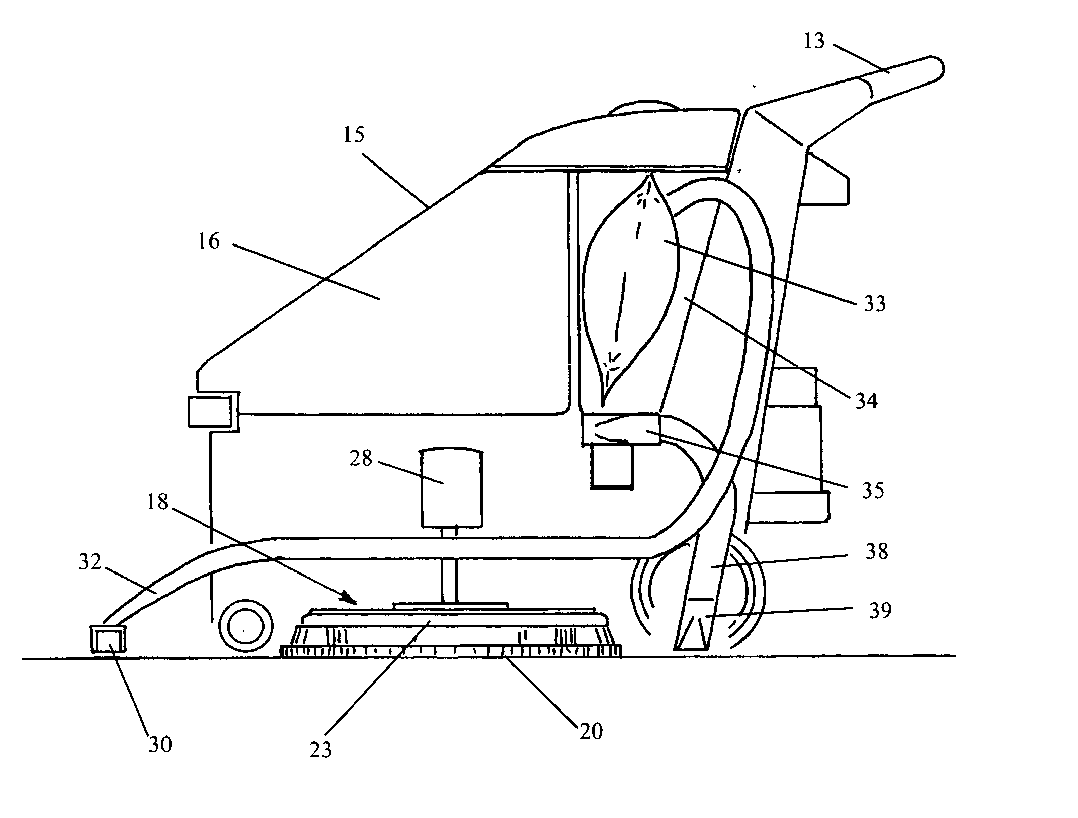
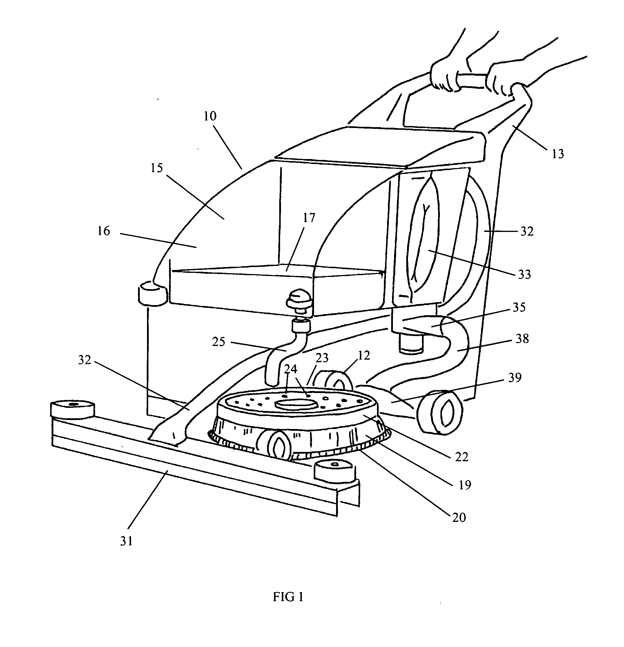
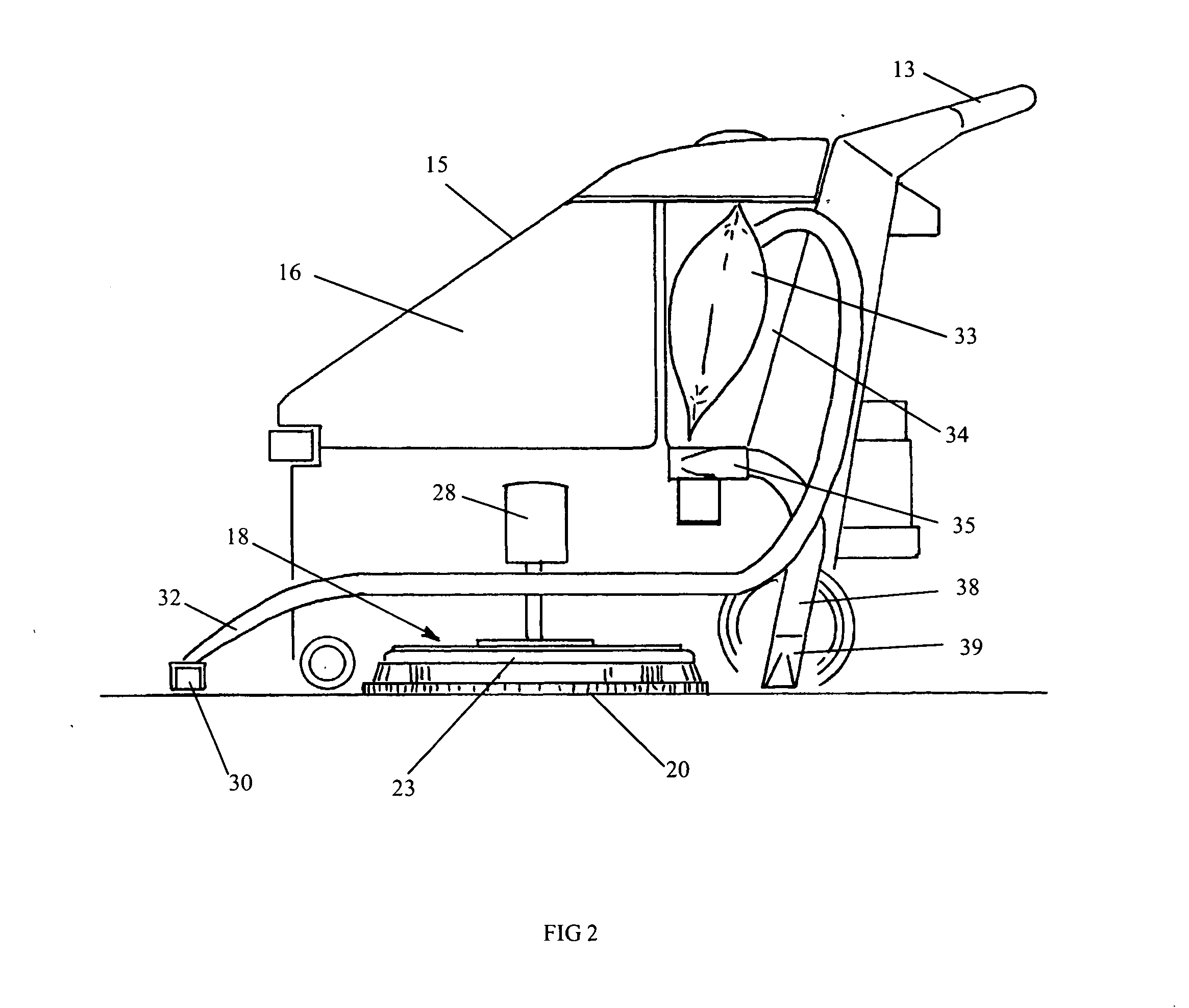
[0019] Referring first to FIG. 1, reference numeral 10 generally designates a floor scrubbing machine having a frame for supporting the various elements. The machine 10 includes forward and rear support wheels 12; and in the illustrated embodiment, the wheels are not driven by a motor. Rather, the machine is pushed by an operator standing behind the machine and grasping the handle 13, urging the machine in a leftward direction in FIG. 2 and a generally leftward and slightly toward the viewer in FIG. 1.

[0020] The machine 11 also includes an outer casing 15 in which there is formed a solution tank generally designated 16 for receiving a quantity of liquid cleaning solution or clean water 17. Beneath the machine 10 and carried by the frame is a pad assembly generally designated 18, in FIG. 2, and including a pad driver 19 and a micro fiber pad 20 attached to, or otherwise secured beneath, the pad driver 19.

[0021] The micro fiber pad 20 includes a lower layer of micro fiber sheet mate...


PUM


Abstract

A floor cleaning machine includes a vacuum pick-up in front of the machine for suctioning loose material and debris off the floor. A micro fiber pad assembly is mounted beneath the machine for cleaning the floor following the vacuum pick-up. The micro fiber pad may be motor driven. A source of solution delivers a controlled amount of solution or water to moisten the micro fiber pad. A vacuum motor provides suction to the forward vacuum pick-up, routes the suctioned air through filter, and the filtered air is then delivered to an air diffuser at the rear of the machine to dry any residual moisture behind the micro fiber pad.

Description

RELATED APPLICATION [0001] This application claims the benefit of co-pending, co-owned U.S. Provisional Application No. 60 / 485,521 filed on Jul. 7, 2003 for “FLOOR CLEANING MACHINE USING MICRO FIBER PAD”.FIELD OF THE INVENTION [0002] The present invention relates to floor cleaning machines; and more particularly, it relates to a floor cleaning machine using a micro fiber pad for engaging and scrubbing the floor. BACKGROUND OF THE INVENTION [0003] One widespread procedure for cleaning floors commercially requires that the floor be pre-swept, normally by hand, prior to using a floor scrubbing machine to scrub the floor. Automatic floor scrubbers typically use a water spray or gravity feed from a solution tank applied directly to the floor (after the loose dirt and debris are removed manually or by a separate vacuum machine), followed by a series of brushes which may include cylindrical scrub brushes, a group of disc scrub brushes or a combination of the two, to work the solution into ...

Claims


Application Information

Patent Timeline
IPC IPC(8): A47L11/20A47L11/202A47L11/293
CPCA47L11/201A47L11/2025A47L11/293A47L11/4097A47L11/4038A47L11/4044A47L11/4027
Inventor RAU, MICHAEL A.HOLLY, DAVID R.
Owner MINUTEMAN INT
Why Eureka
Try Eureka