

Cross-flow ion mobility analyzer
- Summary
- Abstract
- Description
- Claims
- Application Information
AI Technical Summary
Benefits of technology
Problems solved by technology
Method used
Image

Examples
Embodiment Construction
Reference will now be made to the drawings in which the various elements of the present invention will be given numerical designations and in which the invention will be discussed so as to enable one skilled in the art to make and use the invention. It is to be understood that the following description is only exemplary of the principles of the present invention, and should not be viewed as narrowing the claims which follow.
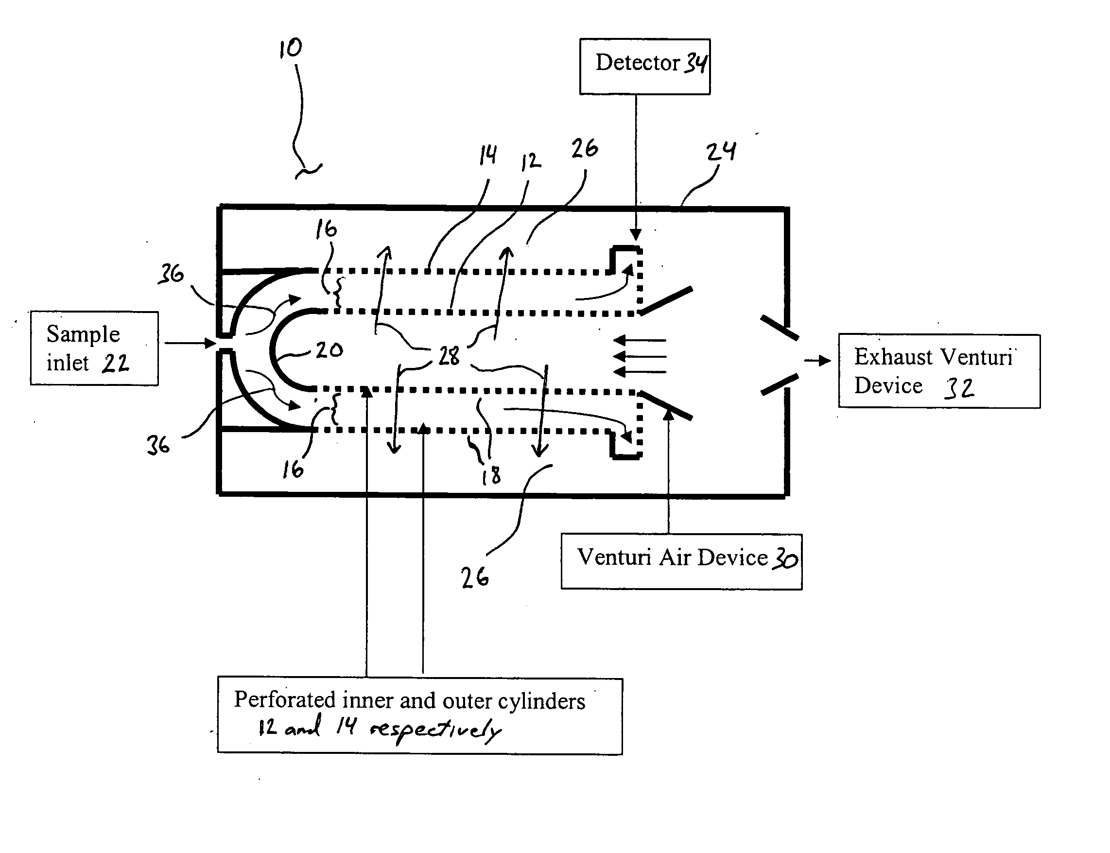
The present invention is a cross-flow ion mobility analyzer (CIMA) that is capable of detecting a wide range of chemicals including pharmaceuticals, environmental pollutants, chemical and biological warfare agents, agrichemicals, and petrochemicals. An immediate need for this technology is airport screening for residues of explosives that may be present on luggage, packages, and personnel. Another useful application is characterizing sizes of lipo-proteins from blood samples. It will be understood by those skilled in the art that there are other applications f...
PUM
 Abstract
Description
Claims
Application Information