Multi-finger hand device

a multi-finger, hand-held technology, applied in the direction of load-engaging elements, program-controlled manipulators, gripping heads, etc., can solve the problems of complicated arrangement of wire elements, disabled other finger mechanisms to perform stretching operations, and disabled to hold objects properly, so as to reduce cost, prevent cost increase, and facilitate bending and stretching operation sequence.

Inactive Publication Date: 2005-01-13
HONDA MOTOR CO LTD
View PDF9 Cites 12 Cited by
  • Summary
  • Abstract
  • Description
  • Claims
  • Application Information

AI Technical Summary

Benefits of technology

[0025] Furthermore, in the second aspect of the present invention, even if the biasing forces of the respective biasing means are set to a constant value, by locating the supporting point of the holding element provided between the two joining elements closer to any one of the joining elements, the bending and stretching operation sequence of the two finger mechanisms belonging to one of the two pairs of the four finger mechanisms and the two finger mechanisms belonging to the other can be set easily. Specifically, for example, when the biasing means of the respective finger mechanisms have the same biasing force and the holding element is moved via the supporting point, firstly, the holding element rocks, and one of the joining elements at a shorter distance from the supporting point starts to move at an earlier timing than the other joining element at a longer distance from the supporting point. At this time, in a case where the respective biasing means bias the respective finger mechanisms to the stretching side, since the wire elements joined to the one joining element moved at an earlier timing are pulled earlier than the wire elements joined to the other joining element, the bending operations of the two finger elements belonging to the one can be started earlier than those of the two finger elements belonging to the other. Furthermore, in a case where the respective biasing means bias the respective finger mechanisms to the bending side, since the wire elements joined to the one joining element moved at an earlier timing are released earlier than the wire elements joined to the other joining element, the two finger mechanisms belonging to the one can start the stretching operations later than the two finger mechanisms belonging to the other. In this way, since the bending and stretching operation sequence of the finger mechanism can be set by the supporting point position of the holding element, cost increase can be prevented by using biasing means having the same biasing force without mounting biasing means having a different biasing force for each finger mechanism.
[0026] Furthermore, in the first and second aspects of the present invention, by locating the supporting point provided between the both joining portions of the joining element closer to any one of the joining portions, the bending and stretching operation sequence can be set easily with respect to the two finger mechanisms. This is basically similar to the above-mentioned case of the supporting point position of the holding element, and when the holding element is moved, the joining element rocks around the supporting point and the wire element joined to one joining portion at a shorter distance from the supporting point is pulled at an earlier timing than the wire element joined to the other joining portion at a longer distance from the supporting point.
[0027] In addition, for example, in the multi-finger hand device of the present invention, when the four finger mechanisms correspond to an index finger to a little finger by imitating a human hand, by combining the supporting point position of the joining element and the supporting point position of the holding element, the bending operations from the little finger to the index finger can be continued with a slight sequential delay, so that a natural gripping operation imitating a human hand can be achieved easily.
[0028] Furthermore, in the present invention, it is preferable that the joining element is held by the holding element via a link element provided consecutively and rockably to the holding element. Thereby, even when the holding element is provided closer to the arm in the hand, the joining element can be made closer to the respective finger mechanisms by the link element, whereby the length of the respective wire elements is saved to reduce cost. In addition, the rockable link element can absorb a circular arc activation when the holding element rocks around the supporting point thereof to transmit it as a substantially linear operation to the joining element, and the stable bending and stretching operations of the finger mechanisms can be performed.

Problems solved by technology

However, these conventional multi-finger hand devices, being provided with an actuator for each finger mechanism, can control the bending and stretching operations of the respective finger mechanisms independently, while large space is necessary for mounting a number of actuators.
Furthermore, since the wire element connecting the finger mechanism and the actuator corresponding to the same are required for each finger mechanism, space for arranging a number of wire elements is also necessary and the arrangement of the wire elements becomes complicated.
However, in such a case, for example, when the bending operations of the respective finger mechanisms are performed to hold an object, and one of the finger mechanisms touches the object or another obstacle, thereby being disabled to perform the bending operation further, the other finger mechanisms may also be disabled to perform their bending operations further, thereby being disabled to hold the object properly.
Furthermore, in a case where the respective finger mechanisms are stretched from the bending state, when one of the finger mechanisms touches an obstacle or the like, thereby being disabled to perform the stretching operation further, the other finger mechanisms are also disabled to perform the stretching operations.

Method used


Image

  • Multi-finger hand device
  • Multi-finger hand device
  • Multi-finger hand device

Examples


Embodiment Construction

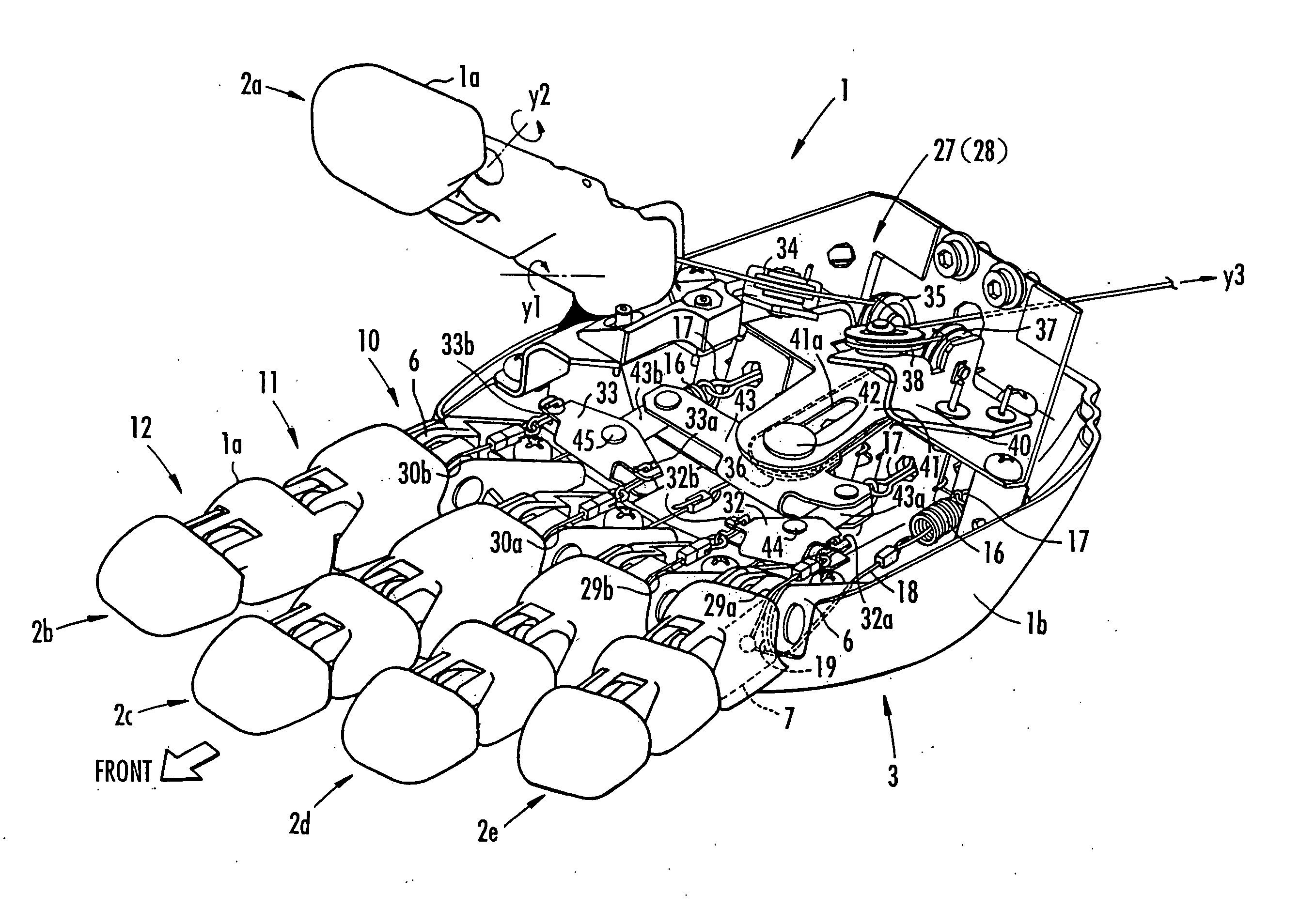
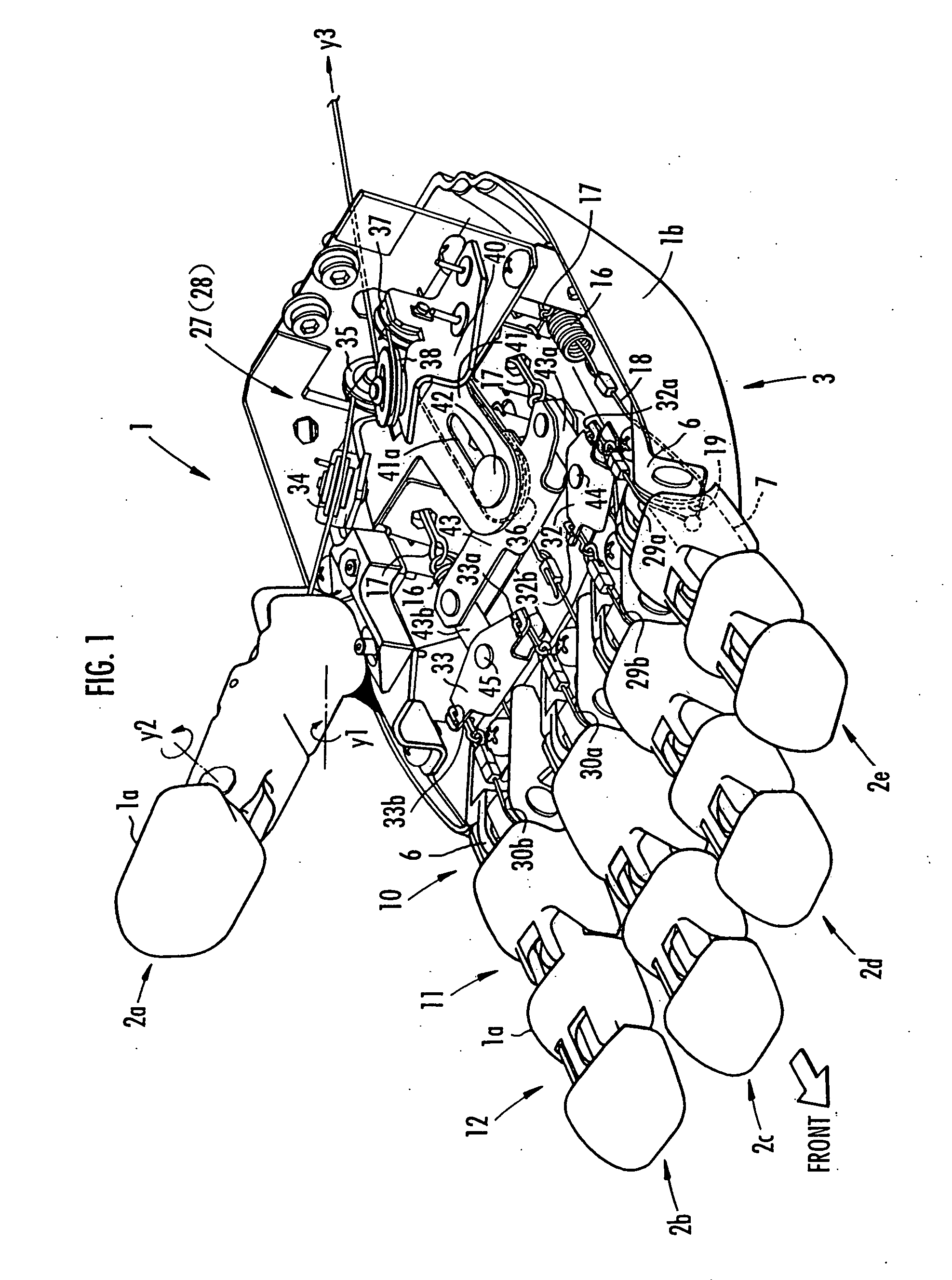
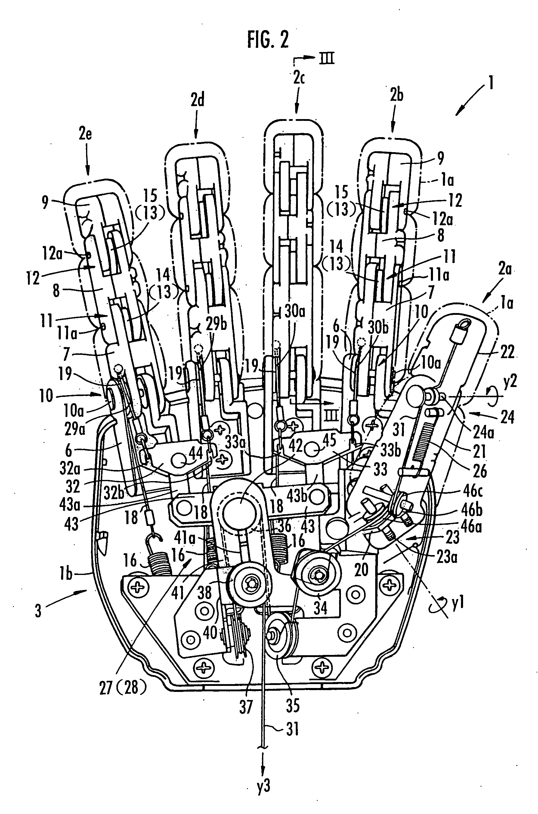
[0046] One embodiment of a multi-finger hand device of the present invention will be described in reference to FIGS. 1 to 6. Incidentally, the present embodiment corresponds to both of the first aspect and the second aspect according to the present invention.

[0047] As shown in FIG. 1, a multi-finger hand device 1 according to the present embodiment is formed by imitating a human hand, comprising five finger mechanisms 2a to 2e corresponding to five fingers and a hand 3 corresponding to a palm. The finger mechanisms 2a to 2e correspond to a thumb, index finger, middle finger, ring finger, and little finger in a human hand, respectively. The hand 3 is joined rotatably via a wrist base 4 to an arm 5, a part of which is shown in FIG. 4. The arm 5 is provided in a robot body of a humanoid or the like, which is not shown in the figure.

[0048] Here, as shown in FIG. 1, each of the finger mechanisms 2a to 2e is covered with a finger cover element 1a in such a manner as to bend and stretch....


PUM


Abstract

There is provided a multi-finger hand device which can perform smooth bending and stretching operations of finger mechanisms in holding work of an object or the like while reducing the number of actuators as driving sources of the bending and stretching operations of the finger mechanisms. Wires 29a and 29b, and wires 30a and 30b extending from the finger mechanisms 2b to 2e biased to the stretching side by springs 16, or the like are joined to joining element 32 and 33, respectively. A wire 31 provided extensionally from the finger mechanism 2a is wound onto a pulley 36 and drawn from the base side of the hand 3. The joining elements 32 and 33 are rockably held by a holding element 43 via spindles 44 and 45. The holding element 43 is provided movably and rockably around a spindle 42. The pulley 36 is held by the holding element 43 and moves together with the holding element 43. By pulling the wire 31, the bending operations of the finger mechanisms 2a to 2e are performed collectively. During bending and stretching operations of the finger mechanisms 2a to 2e, even if any of the finger mechanisms touches an object or the like and is disabled to move, the bending and stretching operations of the other finger mechanisms can be performed.

Description

FIELD OF THE INVENTION [0001] The present invention relates to a multi-finger hand device having a plurality of finger mechanisms. BACKGROUND ART [0002] A multi-finger hand device having a structure similar to that of a human hand is configured such that a plurality of finger mechanisms are provided extensionally from a hand attached to a tip end of an arm, each having a plurality of interjoint elements sequentially connected via a plurality of finger joints. [0003] In this type of multi-finger hand device, there have been known in the prior art those in which, for each finger mechanism, an actuator for driving the finger joints of the finger mechanism is provided apart from the finger mechanism (for example, in the hand or arm), this actuator is connected to the finger mechanism via a wire element and a pulley element onto which the wire element is wound, and the wire element is pulled by the actuator to allow the finger mechanism to perform bending and stretching operations (for e...

Claims


Application Information

Patent Timeline
Patent Type & Authority Applications(United States)
IPC IPC(8): B25J15/08B25J9/10B25J15/00
CPCB25J15/0009B25J9/104
Inventor MATSUDA, HIROSHI
Owner HONDA MOTOR CO LTD
Why Eureka
Try Eureka