Digital duty cycle correction circuit and method for multi-phase clock

a technology of digital duty cycle and correction circuit, which is applied in the direction of pulse duration/width modulation, pulse technique, pulse manipulation, etc., can solve the problems of difficult to correct the duty cycle of a high-speed clock and sensitive to nois

Inactive Publication Date: 2005-01-13
POSTECH ACAD IND FOUND
View PDF3 Cites 60 Cited by
  • Summary
  • Abstract
  • Description
  • Claims
  • Application Information

AI Technical Summary

Benefits of technology

The present invention also provides a digital duty cycle correction circuit and method for a multi-phase clock, in which clock duty cycle correction is not affected by a duty cycle of an input clock signal by using only clock rising edge information for an input clock signal during clock duty cycle correction.

Problems solved by technology

As a result, it is difficult to correct the duty cycle of a high-speed clock and such duty cycle correction is sensitive to noise.

Method used


Image

  • Digital duty cycle correction circuit and method for multi-phase clock
  • Digital duty cycle correction circuit and method for multi-phase clock
  • Digital duty cycle correction circuit and method for multi-phase clock

Examples


Embodiment Construction

Hereinafter, a digital duty cycle correction circuit for a multi-phase clock and method will be described in detail with reference to the accompanying drawings. In the description of the present invention, if detailed descriptions of related disclosed art or configuration are determined to unnecessarily make the subject matter of the present invention obscure, they will be omitted. Terms to be used below are defined based on their functions in the present invention and may vary according to users, user's intentions, or practices. Therefore, the definitions of the terms should be determined based on the entire specification.

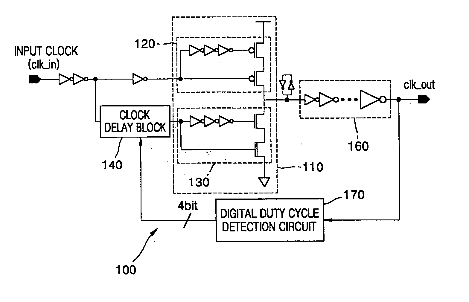
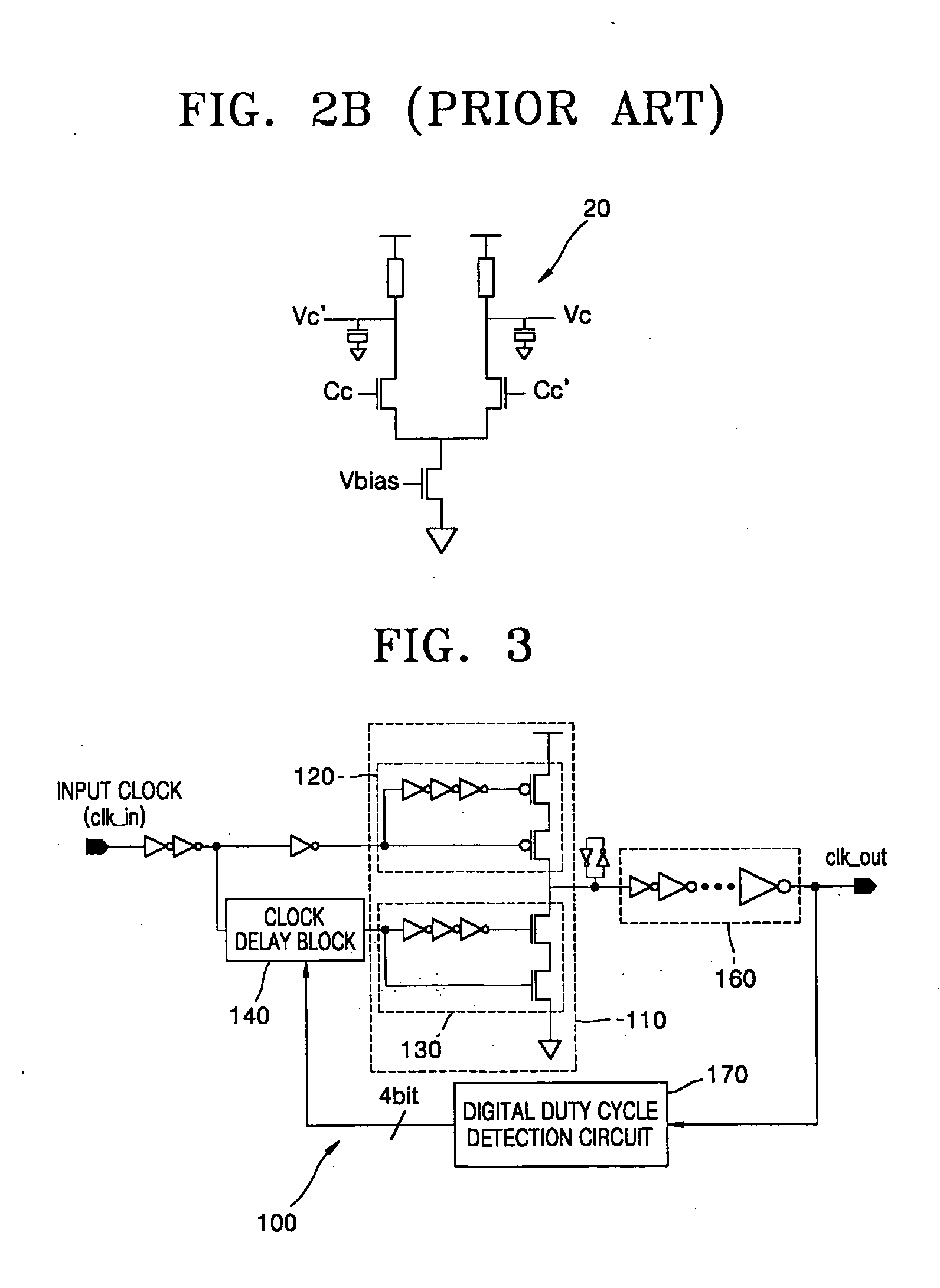
FIG. 3 is a circuit diagram of a digital duty cycle correction circuit for a multi-phase clock according to an embodiment of the present invention, FIG. 4 is a circuit diagram of a digital duty cycle detection circuit of the digital duty cycle correction circuit of FIG. 3, FIG. 5 is a circuit diagram of a current integrator used in the digital duty cycle detecti...


PUM


Abstract

Provided is a digital duty cycle correction circuit and method for a multi-phase clock, in which duty cycle correction information of an input clock signal is stored in a power save state of a system by adopting a digital correction method in a duty cycle correction method for a multi-phase clock and phase information of the input clock signal is held constant during duty cycle correction of the input clock signal by correcting duty cycles of the input clock signal by changing the falling edge of the clock without changing the rising edge of the input clock signal during duty cycle correction of the input clock signal, thereby correcting the multi-phase clock. To this end, the digital duty cycle correction circuit includes a clock delay means that takes the form of a shunt capacitor-inverter, a clock generation means including a clock rising edge generation circuit and a clock falling edge generation circuit, and a digital duty cycle detection means including integrators, a comparator, and a counter/register.

Description

CROSS REFERENCE TO RELATED APPLICATION This application claims the priority of Korean Patent Application No. 2003-46864, filed on Jul. 10, 2003, in the Korean Intellectual Property Office, the disclosure of which is hereby incorporated by reference in its entirety. BACKGROUND OF THE INVENTION 1. Field of the Invention The present invention relates to a digital duty cycle correction circuit and method for a multi-phase clock, and more particularly, to a digital duty cycle correction circuit and method for a multi-phase clock, in which duty cycle correction information of a clock is stored in a power save state of a system by adopting a digital correction method in a duty cycle correction method for a multi-phase clock and it becomes possible to perform correction for the multi-phase clock by maintaining phase information of the clock constant during duty cycle correction of the clock. 2. Description of the Related Art As is well known to those skilled in this field, a clock with...

Claims


Application Information

Patent Timeline
Patent Type & Authority Applications(United States)
IPC IPC(8): H03K5/00H03K3/017H03K5/156
CPCH03K5/1565H03K5/00
Inventor PARK, HONG JUNEJANG, YOUNG CHANBAE, SEUNG JUN
Owner POSTECH ACAD IND FOUND
Why Eureka
Try Eureka