
Writing instrument

a writing instrument and writing technology, applied in the field of writing instruments, can solve the problems of increasing manufacturing costs, and affecting the quality of writing instruments, so as to reduce manufacturing costs, avoid damage, and reduce manufacturing costs

Active Publication Date: 2005-01-13
THE PILOT INK CO LTD
View PDF5 Cites 8 Cited by
  • Summary
  • Abstract
  • Description
  • Claims
  • Application Information

AI Technical Summary

Benefits of technology

[0011] The invention has been devised to overcome the above-described drawbacks of the conventional art, and its object is to provide a writing instrument which makes it possible to secure air passages even in the event that an infant swallows the cap by mistake, and which has no possibility of the pen tip coming into contact with the annular seal portion of the cap when the cap is fitted. Another object of the invention is to provide a writing instrument which has a cap fitting structure that has no possibility of pressurizing the air in the cap and entrainment of air in the ink tank of the writing instrument body during the cap fitting, and which brings down the manufacturing cost and provides the writing instrument at low cost. Still another object of the invention is to provide a writing instrument that makes it possible to avoid causing damage to the annular seal portion during the molding of the cap.

Problems solved by technology

Therefore, when the cap is fitted, there is a possibility of the pen tip coming into contact with the seal portion, with the result that ink can attach to and smear the seal portion or can damage it, possibly causing the occurrence of faulty airtightness.
As a result, the manufacturing cost increases, and it becomes difficult to provide the writing instrument at low cost.
Hence, there is a possibility that proper sealing characteristics cannot be obtained between the annular seal portion and the annular airtight portion of the writing instrument body.

Method used


Image

  • Writing instrument
  • Writing instrument
  • Writing instrument

Examples


first embodiment

[0052] [First Embodiment]

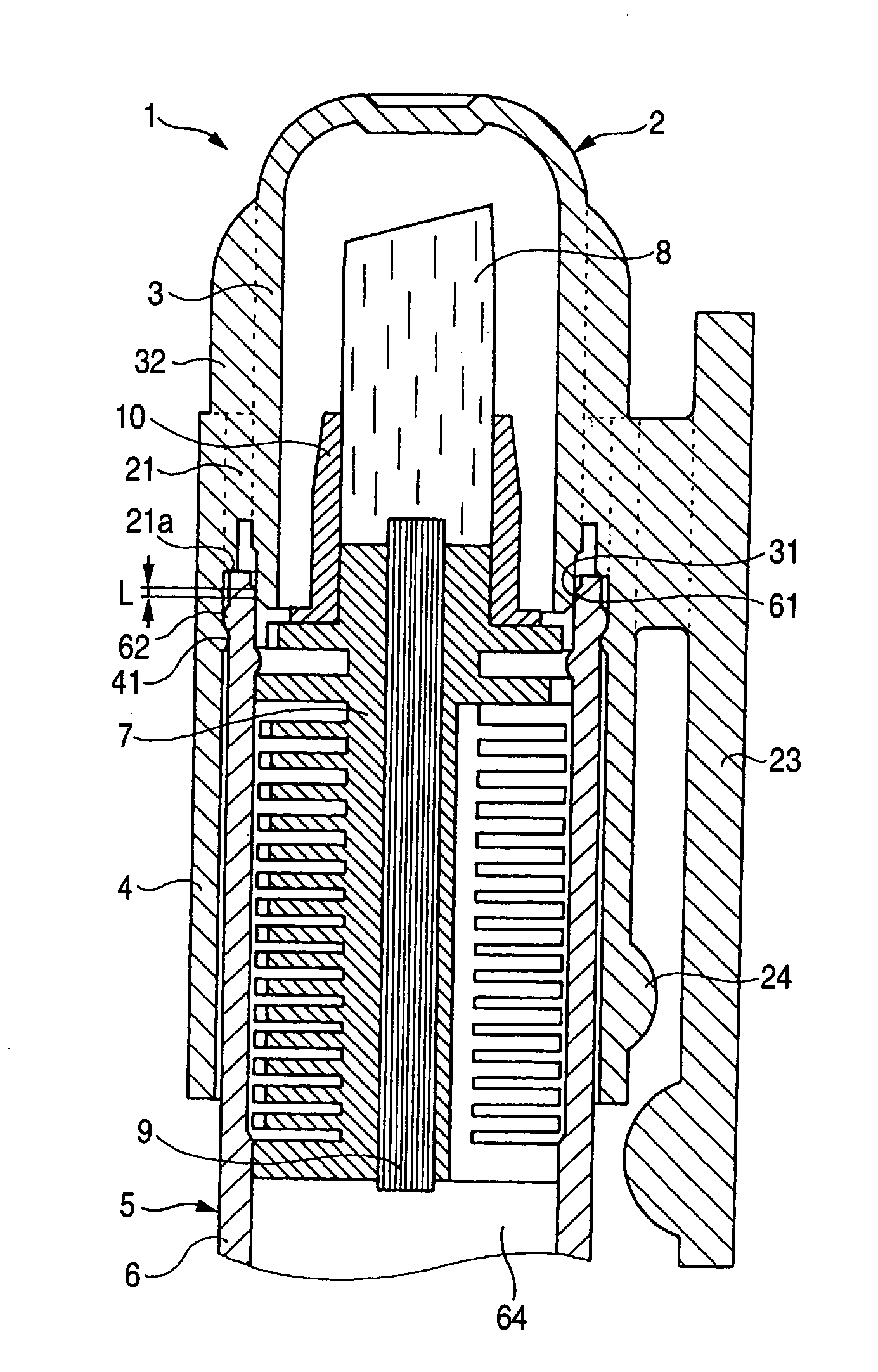
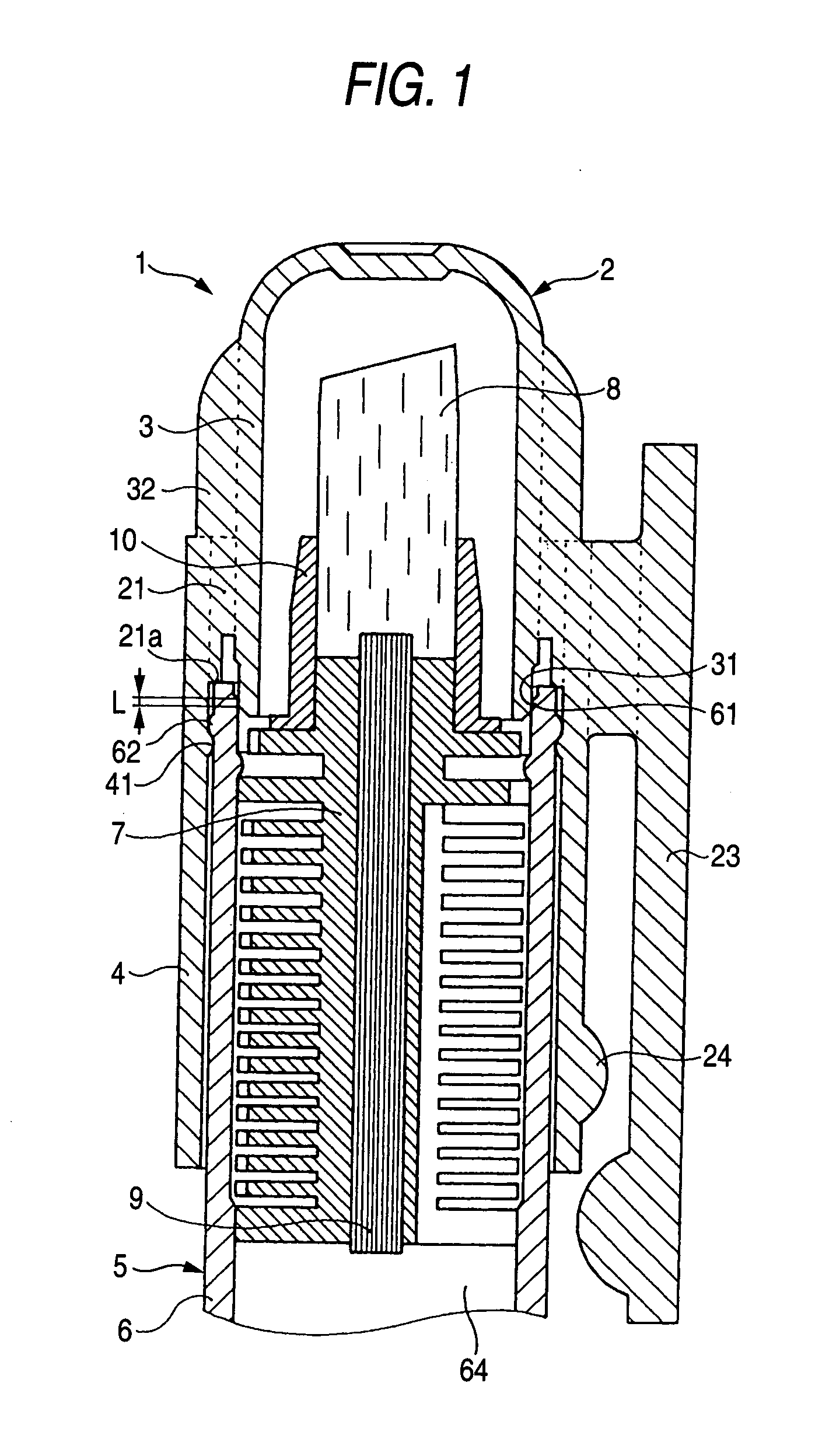
[0053] FIGS. 1 to 6 illustrate a first embodiment of a writing instrument 1 in accordance with the invention. In this embodiment, the writing instrument 1 is comprised of a cap 2 and a writing instrument body 5, the cap 2 being detachably fitted to the pen tip side of the writing instrument body 5. FIG. 1 shows a state in which the cap 2 is fitted on the pen tip side of the writing instrument body 5.

[0054] (Cap)

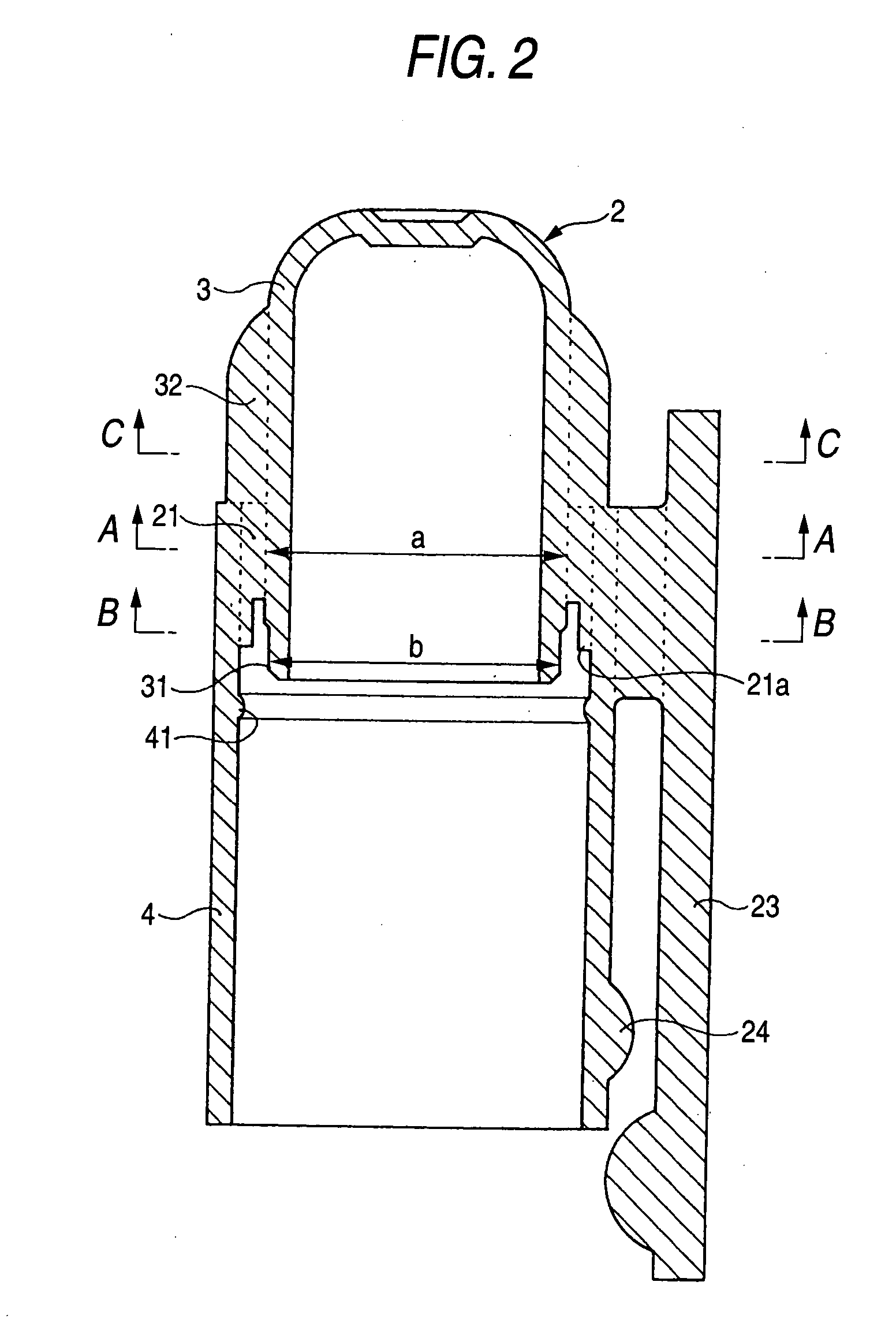
[0055] FIGS. 2 to 5 illustrate the cap 2 in accordance with this embodiment. The cap 2 is obtained by injection molding of a synthetic resin (e.g., polypropylene resin, polyethylene resin, polyester resin, polycarbonate resin, ABS resin, or the like). The cap 2 is comprised of a bottomed cylindrical inner cylinder portion 3 with its front end closed and its rear end open; a cylindrical outer cylinder portion 4 which is connected to an outer peripheral surface of the inner cylinder portion 3 by means of a plurality of connection ribs 21 extending in ...

second embodiment

[0069] [Second Embodiment]

[0070] FIGS. 7 to 9 illustrate a second embodiment of the writing instrument 1 in accordance with the invention. The writing instrument 1 of this embodiment is comprised of the writing instrument body 5 having pen tips (i.e., a first pen tip 8A and a second pen tip 8B) at both ends, as well as two caps (i.e., a first cap 2A and a second cap 2B) which are detachably fitted to the pen tip sides of the writing instrument body 5.

[0071] (First Cap)

[0072] The first cap 2A has a construction substantially similar to that of the first embodiment. Namely, the first cap 2A is obtained by injection molding of a synthetic resin (e.g., polypropylene resin, polyethylene resin, polyester resin, polycarbonate resin, ABS resin, or the like). The first cap 2A is comprised of the bottomed cylindrical inner cylinder portion 3 with its front end closed and its rear end open; the cylindrical outer cylinder portion 4 which is connected to the outer peripheral surface of the inn...

third embodiment

[0094] [Third Embodiment]

[0095] FIGS. 10 to 15 illustrate a third embodiment of the writing instrument 1 in accordance with the invention. In this embodiment, the writing instrument 1 is comprised of the cap 2 and the writing instrument body 5, the cap 2 being detachably fitted to the pen tip side of the writing instrument body 5. FIG. 10 shows a state in which the cap 2 is fitted on the pen tip side of the writing instrument body 5.

[0096] (Cap)

[0097] FIGS. 11 to 14 illustrate the cap 2 in accordance with this embodiment. The cap 2 is obtained by injection molding of a synthetic resin (e.g., polypropylene resin, polyethylene resin, polyester resin, polycarbonate resin, ABS resin, or the like). The cap 2 is comprised of the bottomed cylindrical inner cylinder portion 3 with its front end closed and its rear end open; the cylindrical outer cylinder portion 4 which is connected to the outer peripheral surface of the inner cylinder portion 3 by means of the plurality of connection rib...


PUM


Abstract

A writing instrument has a cap including an inner cylinder portion having an open end and a close end, a cylindrical outer cylinder portion having open ends, a plurality of connection rib integrally connected to an outer surface of the inner cylinder portion and extending in an axial direction and a plurality of vent hole respectively formed between adjacent ones of the connection ribs and a writing instrument body including a pen tip. The open end of the inner cylinder portion extends rearwardly of the connection ribs, the inner cylinder portion seals the pen tip when the cap is fitted on a pen tip side of the writing instrument body and an annular seal portion which is closely contact with an annular airtight portion on the pen tip side of the writing instrument body is provided on the outer peripheral surface of the open end portion of the inner cylinder portion.

Description

[0001] The present invention claims foreign priority to Japanese patent application no. 2004-053200, filed on Feb. 27, 2004 and Japanese patent application no. 2003-271595 filed on Jul. 7, 2003, the contents of which is incorporated herein by reference. BACKGROUND OF THE INVENTION [0002] 1. Field of the Invention [0003] The present invention relates to a writing instrument. It should be noted that, in the invention, the term “front” refers to a closed side of a cap and a pen tip side of a writing instrument body, whereas the term “rear” refers to an open side of the cap and an ink tank side of the writing instrument body. [0004] 2. Description of the Related Art [0005] Conventionally, among the writing instruments of this type, as a cap for a writing instrument which is safe even if an infant swallows it, Japanese Patent Unexamined Publication JP-A-9-39479 discloses “a cap for a writing instrument characterized in that a seal portion for sealing a pen body by coming into close conta...

Claims


Application Information

Patent Timeline
IPC IPC(8): B43K23/08B43K3/00B43K5/00B43K8/02B43K8/03B43K8/06B43K23/12B43K27/08
CPCB43K8/022B43K8/06B43K27/08B43K23/126B43K23/124B43K5/02B43K5/16B43K8/03B43K8/24
Inventor OIKE, SHIGERU
Owner THE PILOT INK CO LTD
Learn More