Device and method for monitoring collisions of a machine component with a workpiece or another machine component

a technology of collision monitoring and workpiece, which is applied in the direction of programming control, instruments, computing, etc., to achieve the effects of preventing production or manufacturing process, effective monitoring of space around tool holders, and reducing production costs

Inactive Publication Date: 2005-01-13
SIEMENS AG
View PDF1 Cites 21 Cited by
  • Summary
  • Abstract
  • Description
  • Claims
  • Application Information

AI Technical Summary

Benefits of technology

[0015] The present invention makes it possible to identify possible collisions before they actually happen. A collision can be prevented by a suitable reaction of the controller. By using sensors, the machine and its components can be monitored based not on idealized assumptions, but instead based on the actual situation in the machine. A collision can then be identified that could not be identified or measured with the conventional methods described above. As a result, the invention provides a reliable and practical collision monitoring method and device which offers protection through the use of sensors to eliminate the possibility of human error.
[0017] According to another feature of the present invention, the distance sensor can be attached to or in the immediate vicinity of the monitored machine component so as to monitor effectively a space around the tool that is currently used. In this way, the employed tool can be monitored directly.
[0018] According to another feature of the present invention, the distance sensor can be attached to or in the immediate vicinity of the monitored machine component so as to effectively monitor a space around a tool holder. In this way, collisions can be purposely monitored in the region around the tool holder.
[0019] According to another feature of the present invention, the distance signal can be a binary signal, because evaluating a binary signal is particularly simple with the employed controller.
[0020] According to another feature of the present invention, the controller can also include a memory for storing position parameters of the workpiece or the other machine component(s), whereby the controller compares a determined distance with the stored position parameters so as to prevent a collision between the machine component and the workpiece or the other machine component if the distance is outside a permissible range or implausible. Alternatively or in addition, the production or manufacturing process can be halted if the workpiece or the other machine component is expected to enter the sensor region of the distance sensor and a distance signal is not detected. By comparing the desired position parameters stored in the controller with the distance signal, an erroneously positioned machine component or workpiece can be quite easily identified.
[0021] Advantageously, the monitored machine component can be prevented from further approaching the workpiece or the other machine component if the distance signal indicates the monitored machine component is outside a permissible range or a plausible distance, thereby preventing the monitored machine component from colliding with the workpiece or with the other machine component. A collision can be reliably prevented by preventing a further approach of the monitored machine component.

Problems solved by technology

Alternatively or in addition, the machine controller stops the production or manufacturing process if the workpiece or the other machine component is expected to enter the sensor region of the distance sensor, but the controller fails to detect a distance signal.

Method used


Image

  • Device and method for monitoring collisions of a machine component with a workpiece or another machine component
  • Device and method for monitoring collisions of a machine component with a workpiece or another machine component

Examples


Embodiment Construction

[0028] Throughout all the Figures, same or corresponding elements are generally indicated by same reference numerals. These depicted embodiments are to be understood as illustrative of the invention and not as limiting in any way. It should also be understood that the drawings are not necessarily to scale and that the embodiments are sometimes illustrated by graphic symbols, phantom lines, diagrammatic representations and fragmentary views. In certain instances, details which are not necessary for an understanding of the present invention or which render other details difficult to perceive may have been omitted.

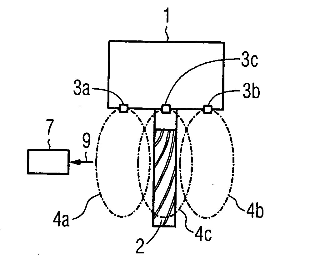
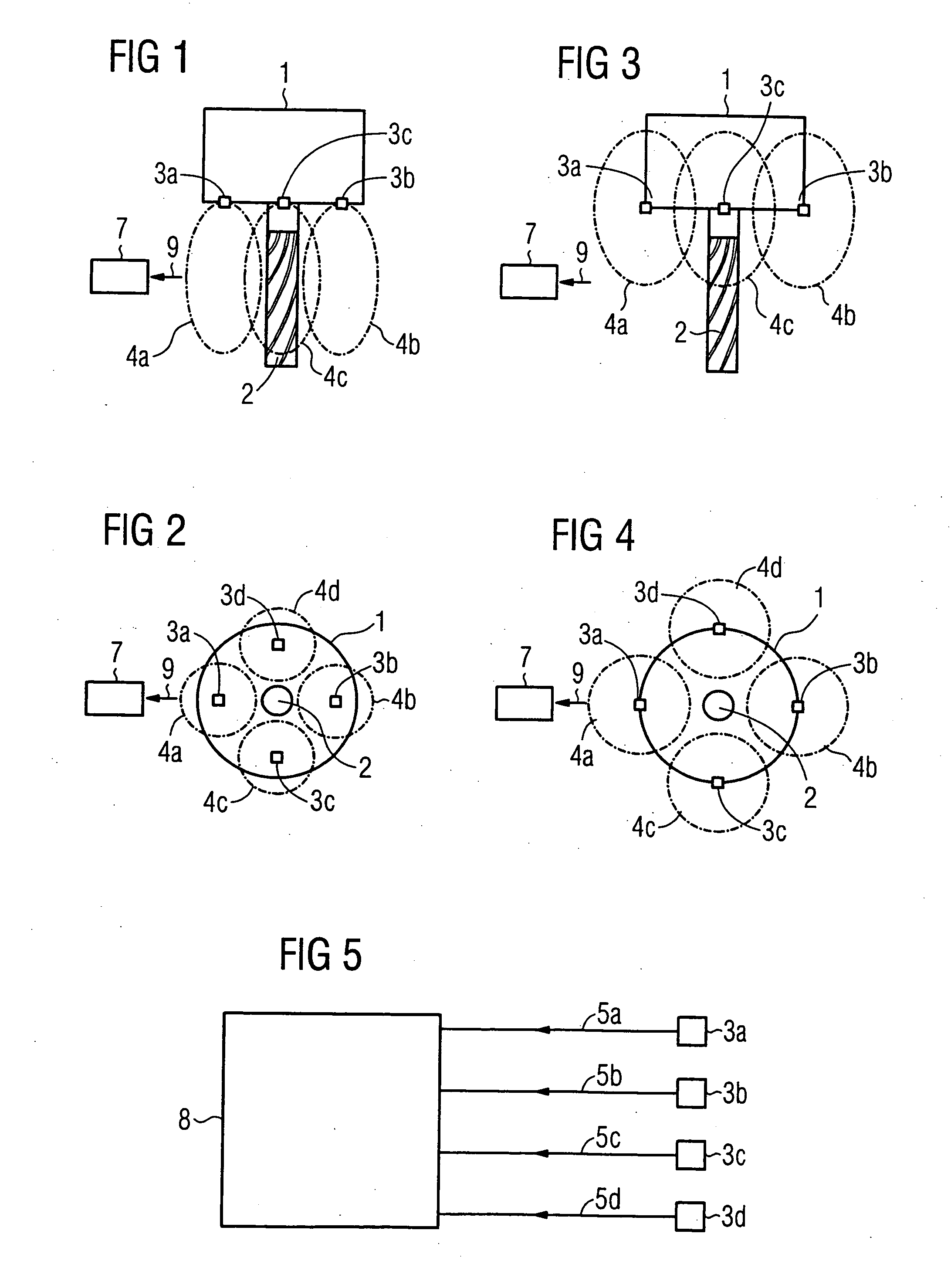
[0029] Turning now to the drawing, and in particular to FIGS. 1 and 2, there is shown schematically a first embodiment of the device for monitoring collisions according to the invention. FIG. 1 shows a tool holder 1 as well as a tool 2 clamped in the tool holder 1 for machining a workpiece 7. The tool holder 1 and the tool 2, which in the illustrated embodiment is implemente...


PUM


Abstract

A device and a method for monitoring collisions between a machine component and a workpiece or another machine component in a machine tool production machine are disclosed. At least one distance sensor is disposed on or in the immediate vicinity of the monitored machine component, whereby the distance sensor generates a distance signal when a tool or another machine component enters the sensor region. The distance signal is transmitted to a machine controller that computes a distance and initiates suitable countermeasures if the distance is outside a permissible range or is otherwise implausible. The device and method are therefore capable of preventatively and reliably detecting a potential collision or the lack of a collision between a machine component and a workpiece or another machine component and initiate appropriate countermeasures.

Description

CROSS-REFERENCES TO RELATED APPLICATIONS [0001] This application claims the priority of German Patent Application, Serial No. 103 27 600.9, filed Jun. 18, 2003, pursuant to 35 U.S.C. 119(a)-(d), the disclosure of which is incorporated herein by reference. BACKGROUND OF THE INVENTION [0002] The present invention relates to a device and a method for monitoring collisions between a machine component and a workpiece or another machine component in a machine tool or production machine. [0003] It is essential to prevent collisions between a machine component of a machine tool or production machine and a workpiece or another machine component. Such collisions can cause substantial damage to the equipment due to the high velocities and the large masses. Accordingly, monitoring collisions provides substantial economic benefits. [0004] Modern machines include collision monitoring systems that cooperate with a tool holder that provides process-related information, for example, in the form of f...

Claims


Application Information

Patent Timeline
Patent Type & Authority Applications(United States)
IPC IPC(8): G05B19/401G05B19/4061G06F19/00
CPCG05B2219/49143G05B19/4061
Inventor KAEVER, MICHAELPULAWSKI, ROBERT
Owner SIEMENS AG
Why Eureka
Try Eureka