Ambient air backflushed filter vacuum

a backflushing filter vacuum and ambient air technology, applied in the direction of cleaning filter means, fluid pressure control, separation processes, etc., can solve the problems of limited flexibility in operating parameters, high cost of backflushing vacuums, and increased maintenance costs, so as to reduce the likelihood of recycling particles through filters

Active Publication Date: 2005-01-20
CHRISTY
View PDF17 Cites 72 Cited by
  • Summary
  • Abstract
  • Description
  • Claims
  • Application Information

AI Technical Summary

Benefits of technology

[0008] In a specially preferred embodiment, the vacuum cleaning machine has a cannister with an opening in its top and an inlet port. A plate closes the opening. The plate has three outlet ports. Three filters are mounted on the plate and disposed inside of the cannister, one in pneumatic communication through a corresponding one of each of the outlet ports. A vacuum source and three valves are also mounted on the plate outside of the cannister. Each valve has a first port in continuously opened pneumatic communication with a corresponding outlet port, a second port in pneumatic communication with the vacuum source and a third port in pneumatic communication with a source of ambient air. A piston reciprocally disposed between the second and third ports is biased by a coil spring to simultaneously close the third port and open the second port in a vacuum mode. A solenoid overcoming the bias reciprocates the piston to simultaneously close the second p

Problems solved by technology

These added components make backflushed vacuums considerably more expensive and more readily subject to malfunction.
Therefore, they have limited flexibility in their operating parameters.
These problems are exacerbat

Method used


Image

  • Ambient air backflushed filter vacuum
  • Ambient air backflushed filter vacuum
  • Ambient air backflushed filter vacuum

Examples


Embodiment Construction

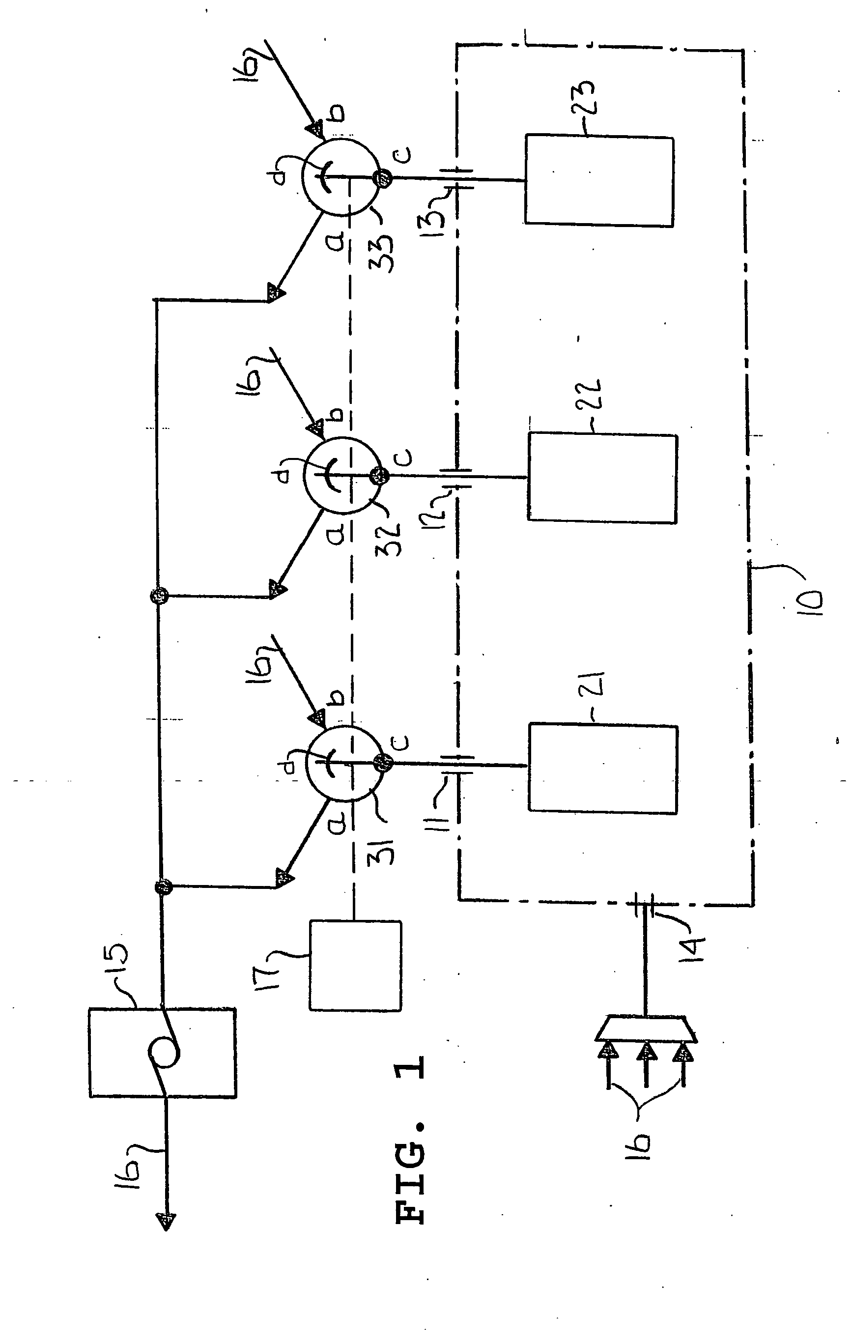
[0021] Turning first to FIG. 1, the ambient air backflushed filter vacuum generally includes a cannister 10 with three, outlet ports 11, 12 and 13 and an inlet port 14. Three filters 21, 22 and 23 are disposed within the cannister 10 and three valves 31, 32 and 33 are disposed outside of the cannister 10. Each of the valves 31, 32 and 33 has a continuously opened port 31c, 32c or 33c which is in constant communication through a respective outlet port 11, 12 or 13 with a respective filter 21, 22 or 23. Each valve 31, 32 and 33 also has two reciprocally opened and closed ports 31a and 31b, 32a and 32b and 33a and 33b, respectively, and an operating mechanism 31d, 32d and 33d, respectively, for switching the valves 31, 32 and 33 between their reciprocal ports “a” and “b”. One reciprocal port “a” of each of the valves 31, 32 and 33 is connected to a vaccum source 15 and the other reciprocal port “b” of each of the valves 31, 32 and 33 is in pneumatic communication with a source of ambie...


PUM

PropertyMeasurementUnit
Fractionaaaaaaaaaa
Fractionaaaaaaaaaa
Fractionaaaaaaaaaa

Abstract

A vacuum cleaning machine has a cannister with an inlet port and at least two outlet ports. At least two filters are disposed inside of the cannister, one in pneumatic communication through each of the outlet ports. At least two valves are disposed outside of the cannister. Each valve is in pneumatic communication between a vacuum source and an outlet port so as to permit air to be drawn by the vacuum source from the inlet port simultaneously through the filters. A controller operates the valves to switch the filters from the vacuum source to ambient air so as to permit ambient air to be sequentially intermittently drawn through corresponding valves and filters into the cannister. Preferably, the controller includes a timing mechanism for setting the delay time of the sequential valve operation and a timing mechanism for setting the intermittent time of connection of each filter to ambient air.

Description

BACKGROUND OF THE INVENTION [0001] This invention relates generally to vacuum cleaning equipment and more particularly concerns a vacuum cleaner having filters backflushed with ambient air. [0002] Cleaning filtered vacuums is presently accomplished by shaker, percussion, forced air or compressed air systems. Such systems periodically apply mechanical or pneumatic forces to dislodge particles collected on the intake surfaces of the filters. To accomplish this, a force system other than the primary vacuum system is required, such as a second blower motor, a compressor or a shaker or percussion system motor. These added components make backflushed vacuums considerably more expensive and more readily subject to malfunction. [0003] Except for very expensive complex 240 volt systems, these systems are mechanically controlled. Therefore, they have limited flexibility in their operating parameters. While their cycle time can be varied, perhaps by changing the rotational speed of a cam, the ...

Claims


Application Information

Patent Timeline
IPC IPC(8): A47L9/20A47L9/28B01D46/00B01D46/04B01D50/00
CPCA47L9/20A47L9/2842A47L9/2857B01D46/0058B01D46/0068G05D16/2066B01D46/4272B01D50/002B01D2279/55A47L9/10B01D46/04Y10T137/86405Y10T137/86895Y10T137/87997B01D46/90B01D46/71B01D50/20B01D46/58B01D46/70A47L5/362A47L9/12B01D45/02G05D16/2073
Inventor MCCUTCHEN, DAVID L.
Owner CHRISTY
Why Eureka
Try Eureka