Annular fuel processor and methods

a fuel processor and annular technology, applied in sustainable manufacturing/processing, gas-gas reaction processes, instruments, etc., can solve the problems of reducing the heating efficiency of a burner and increasing the consumption of fuel sources, so as to facilitate the production of hydrogen, increase the amount of catalyst, and increase the hydrogen output

Active Publication Date: 2005-01-20
ADVENT TECH LLC
View PDF97 Cites 54 Cited by
  • Summary
  • Abstract
  • Description
  • Claims
  • Application Information

AI Technical Summary

Benefits of technology

[0006] The present invention relates to a fuel processor that produces hydrogen from a fuel source. The fuel processor comprises a reformer and burner. The reformer includes a catalyst that facilitates the production of hydrogen from the fuel source. Voluminous reformer chamber designs are provided that increase the amount of catalyst that can be used in a reformer and increase hydrogen output for a given fuel processor size. The burner provides heat to the reformer. One or more burners may be configured to surround a reformer on multiple sides to increase thermal transfer to the reformer.
[0007] Dewars are also described that improve thermal management of a fuel processor by reducing heat loss and increasing burner efficiency. A dewar includes one or more dewar chambers that receive inlet process gases or liquids before a reactor receives them. The dewar is arranged such that inlet process gases or liquids passing through the dewar chamber intercepts heat generated in the burner before the heat escapes the fuel processor. Passing inlet process gases or liquids through a dewar chamber in this manner performs three functions: a) active cooling of dissipation of heat generated in burner before is reaches outer portions of the fuel processor, and b) heating of the air before receipt by the burner, and c) absorbing and recycling heat back into the burner increasing burner efficiency. When the burner relies on catalytic combustion to produce heat, heat generated in the burner warms cool process gases or liquids in the burner according to the temperature of the process gases or liquids. This steals heat from the reformer, reduces heating efficiency of a burner and typically results in greater consumption of the fuel source. The dewar thus pre-heats the incoming process gases or liquids before burner arrival so the burner passes less heat to the process gases or liquids that would otherwise transfer to the reformer.
[0008] In one aspect, the present invention relates to a fuel processor for producing hydrogen from a fuel source. The fuel processor comprises a reformer configured to receive the fuel source, configured to output hydrogen, and including a catalyst that facilitates the production of hydrogen. The fuel processor also comprises a boiler configured to heat the fuel source before the reformer receives the fuel source. The fuel processor further comprises at least one burner configured to provide heat to the reformer and disposed annularly about the reformer. The fuel processor may also comprise a boiler that heats the burner liquid fuel feed.
[0010] In yet another aspect, the present invention relates to a fuel processor for producing hydrogen from a fuel source. The fuel processor comprises a reformer configured to receive the hydrogen fuel source, configured to output hydrogen, and including a catalyst that facilitates the production of hydrogen. The fuel processor also comprises a burner that is configured to provide heat to the reformer. The fuel processor further comprises a dewar that at least partially contains the reformer and the burner and includes a set of dewar walls that form a dewar chamber that is configured to receive an inlet process gas or liquid before the burner receives the inlet process gas or liquid. The fuel processor additionally comprises a housing including a set of housing walls that at least partially contain the dewar and provide external mechanical protection for the reformer and the burner.

Problems solved by technology

This steals heat from the reformer, reduces heating efficiency of a burner and typically results in greater consumption of the fuel source.

Method used


Image

  • Annular fuel processor and methods
  • Annular fuel processor and methods
  • Annular fuel processor and methods

Examples


Embodiment Construction

[0033] The present invention is described in detail with reference to a few preferred embodiments as illustrated in the accompanying drawings. In the following description, numerous specific details are set forth in order to provide a thorough understanding of the present invention. It will be apparent, however, to one skilled in the art, that the present invention may be practiced without some or all of these specific details. In other instances, well known process steps and / or structures have not been described in detail in order to not unnecessarily obscure the present invention.

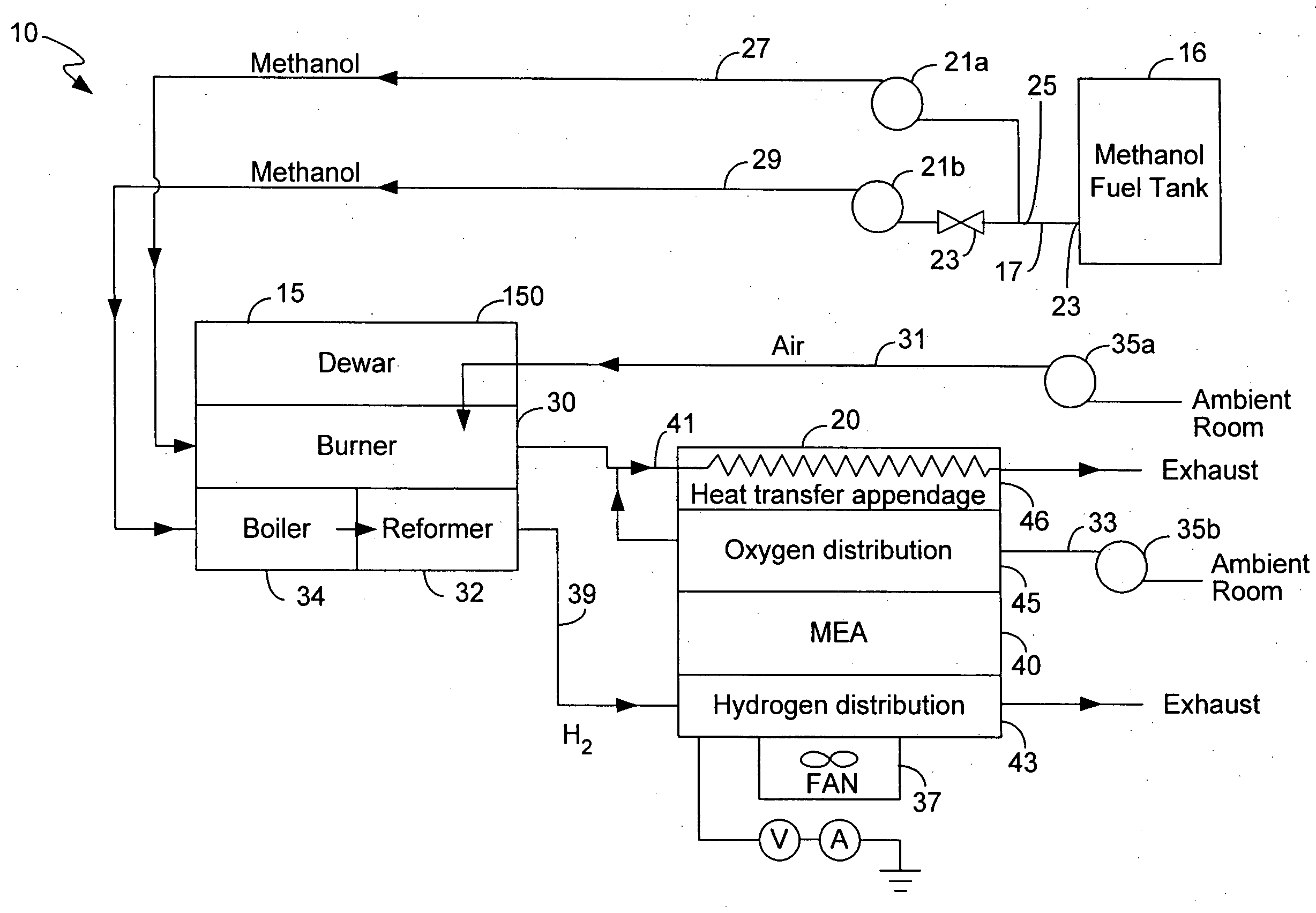
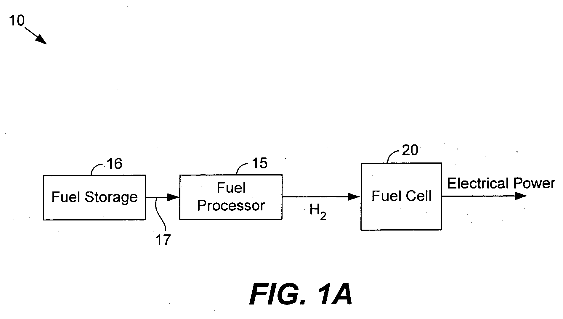
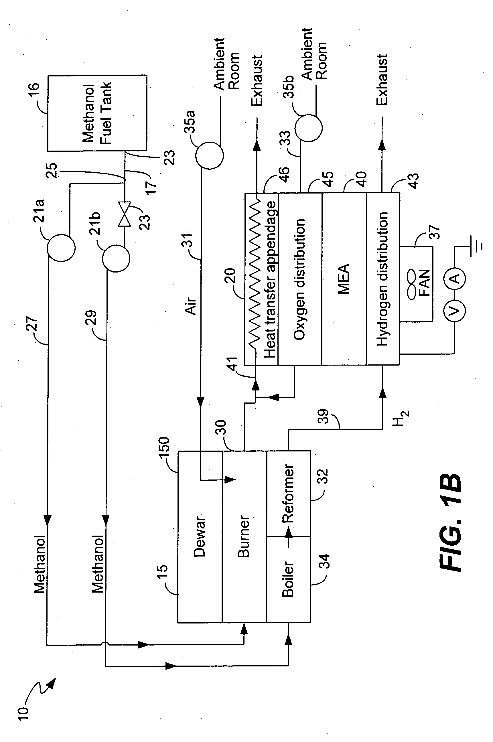
[0034]FIG. 1A illustrates a fuel cell system 10 for producing electrical energy in accordance with one embodiment of the present invention. Fuel cell system 10 comprises storage device 16, fuel processor 15 and fuel cell 20.

[0035] A ‘reformed’ hydrogen supply processes a fuel source to produce hydrogen. As shown, the reformed hydrogen supply comprises a fuel processor 15 and a fuel source storage device...


PUM

PropertyMeasurementUnit
volumeaaaaaaaaaa
volumeaaaaaaaaaa
volumeaaaaaaaaaa

Abstract

Described herein is a fuel processor that produces hydrogen from a fuel source. The fuel processor comprises a reformer and burner. The reformer includes a catalyst that facilitates the production of hydrogen from the fuel source. Voluminous reformer chamber designs are provided that increase the amount of catalyst that can be used in a reformer and increase hydrogen output for a given fuel processor size. The burner provides heat to the reformer. One or more burners may be configured to surround a reformer on multiple sides to increase thermal transfer to the reformer. Dewars are also described that increase thermal management of a fuel processor and increase burner efficiency. A dewar includes one or more dewar chambers that receive inlet air before a burner receives the air. The dewar is arranged such that air passing through the dewar chamber intercepts heat generated in the burner before the heat escapes the fuel processor.

Description

CROSS-REFERENCE TO RELATED APPLICATIONS [0001] This application claims priority under 35 U.S.C. §119(e) from co-pending U.S. Provisional Patent Application No. 60 / 482,996 entitled “Fuel cell system startup procedure and self-heating apparatus”, which is incorporated by reference for all purposes; and also claims priority under 35 U.S.C. §119(e) from co-pending U.S. Provisional Patent Application No. 60 / 483,416 entitled “Fuel Preheat in Portable Electronics Powered by Fuel Cells”, which is incorporated by reference for all purposes.BACKGROUND OF THE INVENTION [0002] The present invention relates to fuel cell technology. In particular, the invention relates to fuel processors that generate hydrogen and are suitable for use in portable applications. [0003] A fuel cell electrochemically combines hydrogen and oxygen to produce electricity. The ambient air readily supplies oxygen. Hydrogen provision, however, calls for a working supply. Gaseous hydrogen has a low energy density that reduc...

Claims


Application Information

Patent Timeline
Patent Type & Authority Applications(United States)
IPC IPC(8): B01J3/00B01J8/00B01J8/02B01J8/04B01J12/00B01J15/00B01J19/24C01B3/32C08F4/636C08F4/649C08F4/651C08F4/654C10J1/00H01MH01M8/04H01M8/06
CPCB01B1/005Y02E60/50B01J8/0496B01J12/007B01J15/005B01J19/2485B01J19/249B01J19/2495B01J2208/00203B01J2208/00221B01J2208/00309B01J2208/00495B01J2208/00504B01J2208/0053B01J2208/00672B01J2219/00157B01J2219/00159B01J2219/00783B01J2219/00788B01J2219/00804B01J2219/00822B01J2219/00824B01J2219/00828B01J2219/00835B01J2219/0086B01J2219/00862B01J2219/00869B01J2219/00871B01J2219/00873B01J2219/00997B01J2219/1923B01J2219/1943B01J2219/2453B01J2219/2458B01J2219/2459B01J2219/2462B01J2219/2465B01J2219/2479B01J2219/2481B01J2219/2485B01J2219/2493B01J2219/2497C01B3/323C01B2203/0233C01B2203/0244C01B2203/0261C01B2203/066C01B2203/0811C01B2203/0816C01B2203/0822C01B2203/0827C01B2203/0844C01B2203/1223C01B2203/1288C01B2203/142C01B2203/82G06F1/26H01M8/04022H01M8/0618H01M8/0631H01M2008/1095B01J8/0285Y02P20/10Y02P20/129
Inventor KAYE, IAN W.SOMOGYVARI, ARPAD
Owner ADVENT TECH LLC
Why Eureka
Try Eureka