
Cove elements and floor coatings and methods for installing

a technology applied in the field of cove elements and floor coatings and methods for installing, can solve the problems of laborious and time-consuming, difficult to keep corners clean and the area where walls meet flooring clean, etc., and achieve the effect of less expensive installation

Inactive Publication Date: 2005-01-20
STANDAL DOUGLAS J +1
View PDF48 Cites 83 Cited by
  • Summary
  • Abstract
  • Description
  • Claims
  • Application Information

AI Technical Summary

Benefits of technology

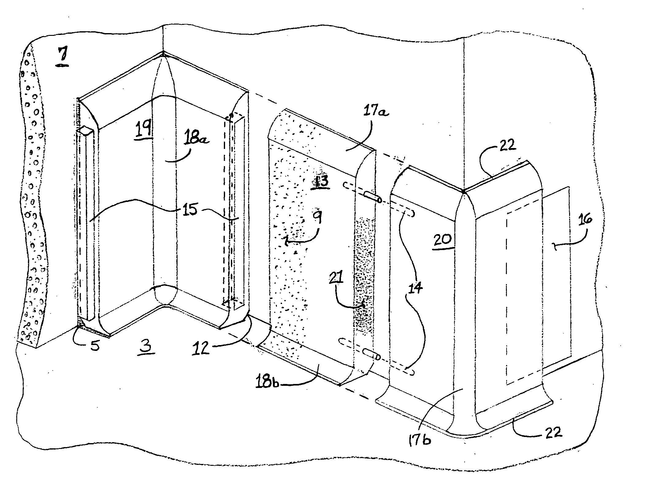
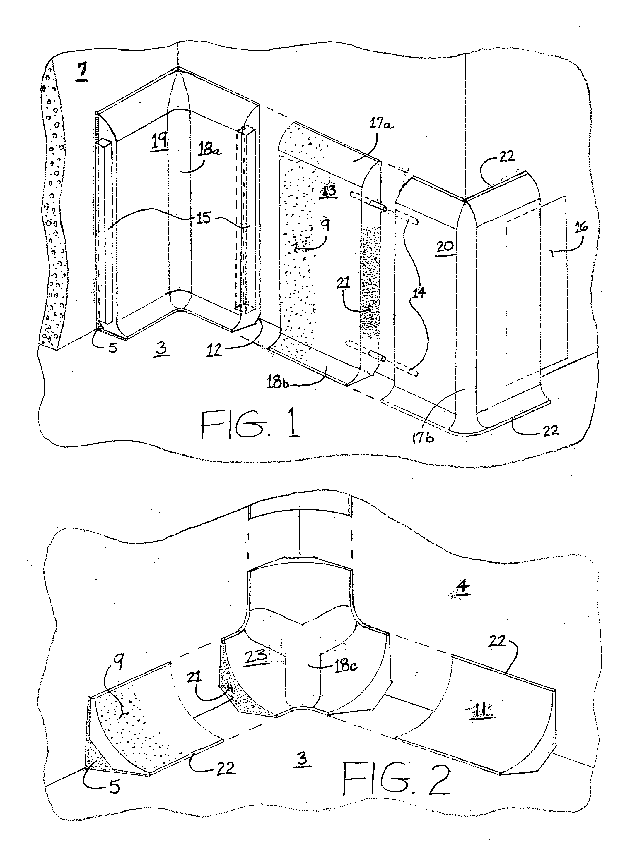
[0016] The goal of this invention is to provide a cove base and stem wall cap molding system for every application of the cementitious floor coating (both solvent and water based) industry. These systems will be faster, easier, less expensive to install, suitable for mass production, and that form or result in a monolithic floor-to-base cove system as much as is possible.
[0018] Accordingly, there are several objects and advantages of the invention. For example, the invention may reduce or eliminate the slow and burdensome troweled base cove method; significantly reduces base cove installation time, which should lower the cost and help the general contractor to expedite the entire job.
[0019] The present invention significantly reduce base cove installation labor costs by enabling any reasonably skilled laborer to install it using the following common tools: a pencil; speed square; sheetrock rasp; carbide or diamond bladed circular saw—corded or cordless; tile saw; miter saw; caulking gun; and corded or cordless drill.
[0020] The invention also enables flooring contractors to use their own employees for base cove installation and avoid the delays and expense of having to hire additional subcontractors.
[0021] The present invention also enhances the finished appearance of all cementitious floor coatings with a more straight, streamlined and uniform base cove shape.
[0022] The present invention more closely meets the industry's requirement for a monolithic installation over the existing trowel method because the systems can have a stronger bond to the floor than to the wall by using different adhesives. This enables the base cove molding to move with the floor as a unit, thus further guaranteeing the seamless integrity of the finish coating during expansion and contraction of wall and / or floor.

Problems solved by technology

A problem with such floors, in particular in commercial and industrial applications, is the difficulty associated with keeping corners clean and keeping the area where walls meet the flooring clean.
However, the requirements regarding covings along the lower portions of a cementitious floor present problems for contractors and builders.
It is a laborious and time consuming job, and is therefore an extremely expensive component of monolithic cementitious floor systems.
For cementitious sub-flooring, expansion and contraction rates are a particular problem, making impractical to use these commercially produced moldings.
Further, the shapes of such moldings do not include a radius or curved contour that is desired for ease of cleaning and in many jurisdictions, as required by recently implemented building codes and regulations.
However, insofar as the inventors are aware, none are made with radius or cant cove at their base or corners that would meet the resinous flooring industry standards.
However, such ceramic tiles, once installed, have grout seams; they are typically glazed making them unsuitable for coating with a resinous flooring material; and cannot provide the seamless floor required by most building codes where monolithic flooring is required.
This entire process has several problems: these technicians are very expensive; their process use a very slow and disruptive to the entire jobsite; such technicians are very hard to find and typically will not do small jobs such as bathrooms and small commercial kitchens; and their troweling techniques do not work well for cove bases higher than 4″ because the mixture will not stay on the wall long enough to set up and harden.
In so far as the inventors are aware, there are no other feasible methods to create this base coving being used by this quickly evolving sector of the industry.

Method used


Image

  • Cove elements and floor coatings and methods for installing
  • Cove elements and floor coatings and methods for installing
  • Cove elements and floor coatings and methods for installing

Examples


Embodiment Construction

[0062] Definition of Terms

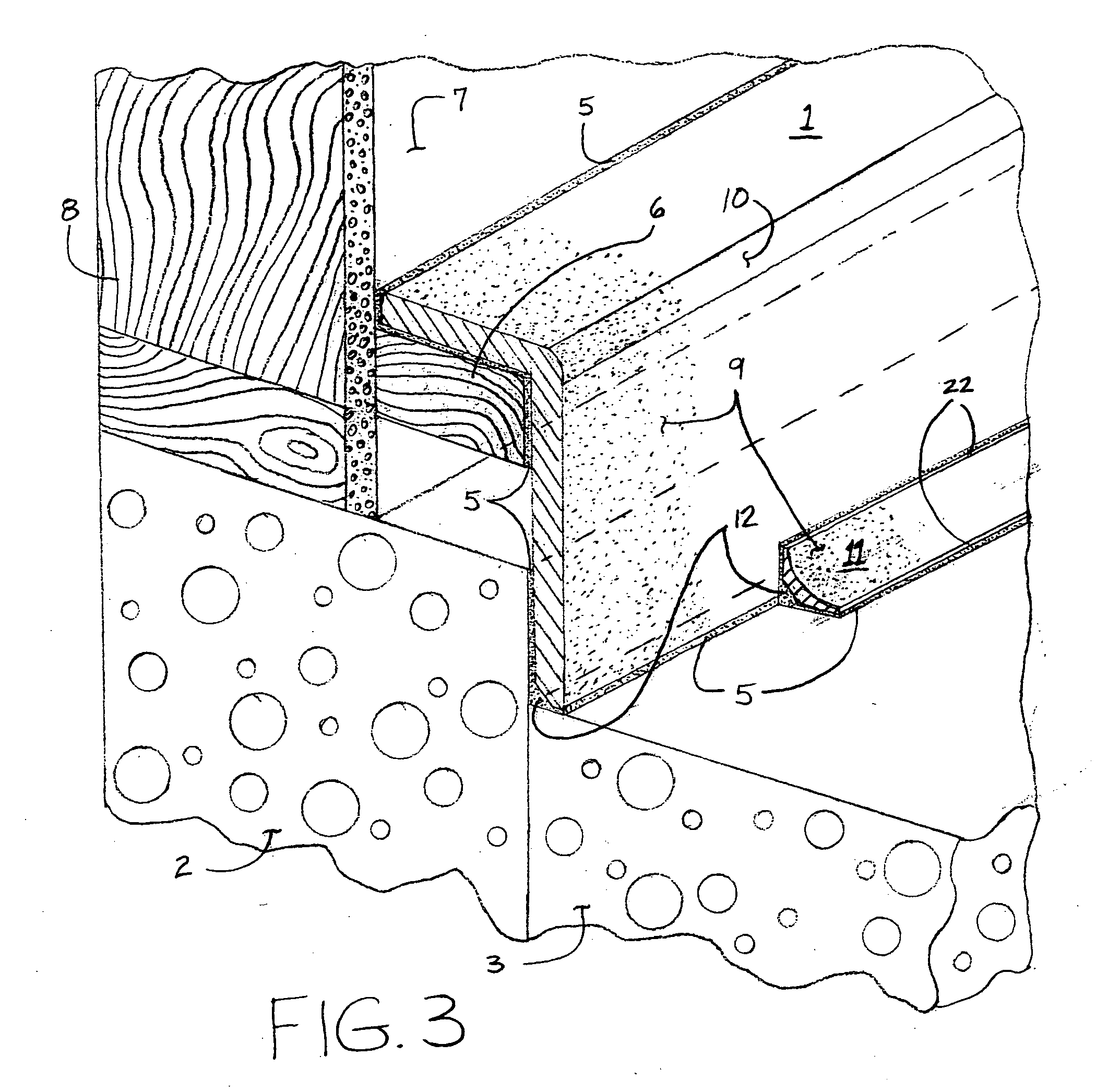
[0063] The term monolithic flooring system used herein refers to a flooring system that includes an under-layment or substrate of material that is rigid and generally uniform, such as cement, concrete or other cementitious or cement-like material (but is not limited to such materials), where the under-layment or substrate is coated with a resinous floor coating. Monolithic flooring systems may include manually formed floor-to-cove transitions along a wall at the floor, or may include the coving members of the present invention installed at the floor and wall junction, attached to either the floor or the walls, with the floor-to-cove transitions or coving members of the present invention are also coated along with the under-layment with the resinous floor coating.

[0064] The term resinous floor coating or coatings refers to any of a variety of materials for coating floors, and in particular, cementitious floors. Resinous floor coatings include epoxies, poly...


PUM

PropertyMeasurementUnit
Angleaaaaaaaaaa
Radiusaaaaaaaaaa
Radiusaaaaaaaaaa

Abstract

Described herein is a monolithic flooring system that includes cove elements that are shaped to provide a transition between floor and wall such that a floor coating may be installed over the cove elements and sub-flooring to create a unitary floor-cove covering making for a surface that is more sanitary and easier to clean. Also described are various shaped cove elements that enable creation of a good transition between wall and floor. The cove elements are preferably made of material similar to the sub-floor, for instance a cementitious material. The floor coating is preferably a resinous material.

Description

CROSS-REFERENCE TO RELATED APLICATIONS [0001] The instant application claims priority to U.S. Ser. No. 60 / 487,517 filed Jul. 14, 2003BACKGROUND OF THE INVENTION [0002] A. Field of the Invention [0003] The invention relates to coving materials for use with resinous floor systems, and further relates to methods of installing such coving materials and formation of resinous floor systems coating cementitious floors and cove elements to form a monolithic flooring structure. The invention further relates to monolithic floor systems that include wall cove elements coated along with the floor with resinous flooring compositions to form a monolithic floor system. [0004] B. Description of the Related Art [0005] Resin based floors are becoming increasingly more popular because of their high performance in impact, abrasion, and chemical resistance. In commercial applications, such floors are rapidly becoming an industry standard, and many building codes now require such floor coatings. An advan...

Claims


Application Information

Patent Timeline
IPC IPC(8): B28B1/14B28B5/02B28B7/00E04F19/04
CPCB28B1/14B28B5/027B28B7/0085E04F2019/0418E04F19/0477E04F19/0495E04F19/045
Inventor STANDAL, DOUGLAS J.ZACHER, DANIEL G.
Owner STANDAL DOUGLAS J
Learn More