Method and apparatus for concealed installation of wires, cables, fibers, pipes and the like within a structure

a technology for installing pipes and wires, which is applied in the direction of electrical equipment, etc., can solve the problems of no convenient equipment or methods for later adding or changing low voltage wiring, and no convenient methods and equipment for initially housing low voltage wires and cables, etc., to facilitate bending and shape forming, easy to cut or saw multiple pieces, and easy to paint

Inactive Publication Date: 2009-08-13
MASSEY MIKE L
View PDF3 Cites 1 Cited by
  • Summary
  • Abstract
  • Description
  • Claims
  • Application Information

AI Technical Summary

Benefits of technology

[0017]The flat conduit is a one piece, flat, flexible thin material made from plastic, paper fiber, metal, polyvinyl or the like that can be shipped, stored, cut and transported around warehouses, construction sites or buildings in a flat state, then prior to shipping or during installation may be shaped to create a conduit or raceway. Unlike conventional conduit, multiple sections may be cut to similar lengths when necessary since they can be stacked, making cutting or sawing of multiple pieces easier. Using the appropriate material, the surface can be made easily paintable so it can be installed on finished surface walls of existing buildings as easily as inside walls or cavities during new construction.
[0018]Indentations or slots are scored into the material and run along the length of the flat conduit to facilitate bending and shape forming during installation. The scoring may be done at the time of manufacture or may be done at the installation site. Each indentation may be positioned in relation to its adjacent indentation to vary the length of the section created by the angular bending of the material along the scoring. The angle of the bend along with the position of the scoring and number of scores in the material permit a wide range of shapes and sizes for the finished conduit. This allows for a customized look and installation in a variety of situations, such as in an existing wall or prior to drywall installation in a new construction. In addition, the positioning of multiple scorings in close proximity to each other allows for a rounded bending of the conduit, for situations where a rounded conduit is appropriate.
[0019]It is therefore an object of the present invention to provide a conduit that is less expensive to manufacture, handle, install, package, store and ship than conventional round, rectangular or square conduits.
[0020]It is a further object of the present invention to provide a conduit that may be easily installed in new construction or remodeling projects.

Problems solved by technology

In the construction of homes, buildings and other structures, there are a lack of convenient methods and equipment for initially housing low voltage wires and cables, such as that used for telephone, television, computer networking, etc.
There is also no convenient equipment or methods existing for the later adding or changing of low voltage wiring and cabling.
However, using these conduits presents several problems.
One problem is that round conduits are expensive to produce, store and ship.
Prior to being cut and installed, round pre-shaped conduits are bulky and take up significant space.
Because pre-shaped round conduit must contain a hollow space for the enclosure of wires, cables, and the like, this increases the overall size of the conduit because of the space the hollow portion displaces.
While this hollow portion does not increase the weight of the conduit, it does increase the size of the conduit.
This increased size leads to higher storage and shipping costs.
Also, because of their round shape and length, they are cumbersome to handle and awkward to move from place to place before and during installation.
An additional problem with round conduit is the difficulty in cutting sections for use.
The hollow created by the round shape makes it difficult or impractical to stack and cut more than one section at a time since the surface area being cut is spread out by the hollow interior of the conduit.
Another problem with pre-shaped round conduit is that it does not have its own integrated attachment method which can be used to fasten it to walls, beams, joists or other parts of a structure.
Another disadvantage to pre-shaped round conduit is that it is usually manufactured in standard sizes of 0.75 inches or 1.0 inches diameter, primarily because of the cost of the material used to manufacture it and the industry need for standardization.
This diameter makes it difficult to add additional wiring later.
It also does not allow for storing excess wiring or cable within the conduit during the “rough-in” phase.
If stored in a gang box, the only way to protect the excess wire or cable is by physically covering the gang box, which may not be effective if high pressure spraying is used to apply paint or other surfacing material.

Method used


Image

  • Method and apparatus for concealed installation of wires, cables, fibers, pipes and the like within a structure
  • Method and apparatus for concealed installation of wires, cables, fibers, pipes and the like within a structure
  • Method and apparatus for concealed installation of wires, cables, fibers, pipes and the like within a structure

Examples


third embodiment

[0047]In FIG. 9, finished conduit 10 is shown. The previously flat conduit 10 containing a plurality of tightly spaced scored indentations 16 (not shown in FIG. 9) are evenly and uniformly bent so that the scored indentations 16 collapse in on each other creating a round bend 20, forming a conduit with a rounded cavity 46. The attachment section 48 and the attachment section 50 are created by angularly bending the conduit 10 along the scored indentations 16 (not shown in FIG. 9) outwardly from the longitudinal axis of conduit 10 to form and angular bend 44 and an angular bend 42.

first embodiment

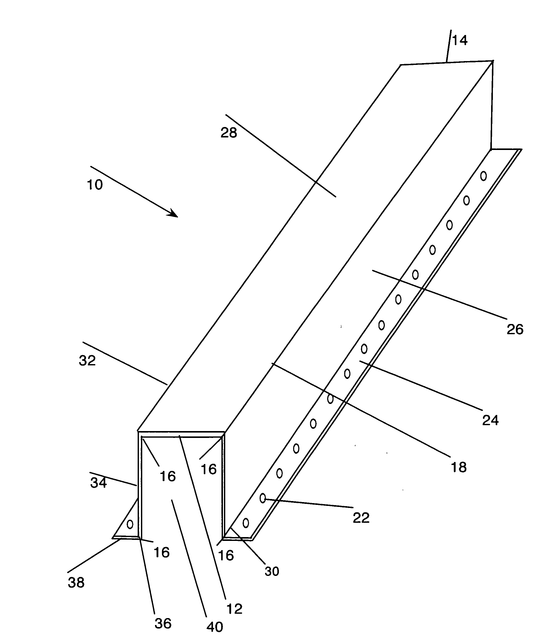
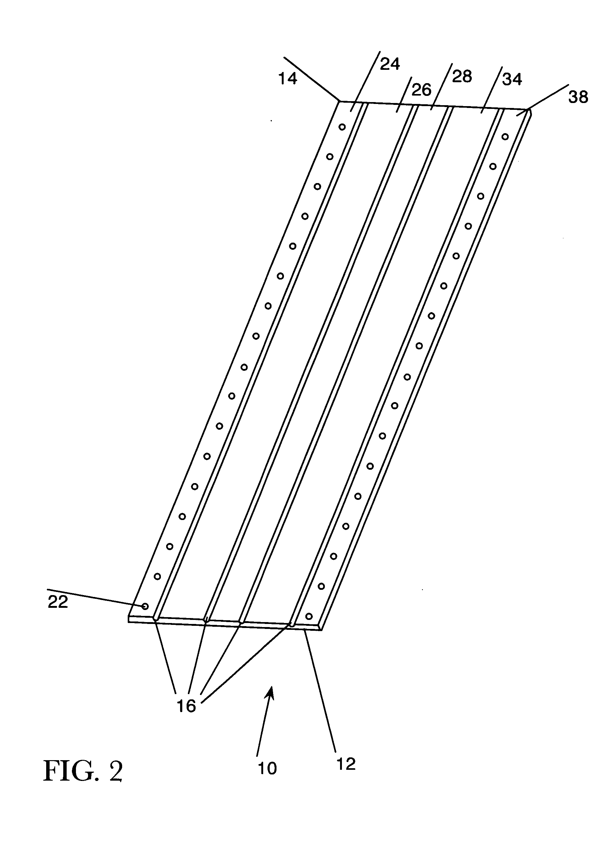
[0048]In FIG. 10, the conduit 10 prior to installation and shaping is shown. The conduit 10 is scored along scored indentations 16 and is placed upon a mounting surface 53 for attachment. A plurality of fasteners 51 are placed through the openings 22 disposed within the attachment section 24 of the conduit 10. The fasteners 51 are driven into the mounting surface 53, thereby securing the conduit 10 to the mounting surface 53. While the fasteners 51 shown being used for securing the conduit 10 are nails, any suitable fastening device, such as staples or screws may be used.

[0049]In FIG. 11, the conduit 10 is shown secured to the mounting surface 53 by means of the fasteners 51. The conduit 10 has been bent at an angle at the bend 30 along scored indentation 16, forming the attachment section 24 and beginning the formation of the side section 26.

[0050]In FIG. 12, the conduit 10 is shown secured to the mounting surface 53 through the attachment section 24 by means of the fasteners 51. T...


PUM


Abstract

A method and apparatus for concealing and installing wires, cables, fibers, pipes and the like within a conduit is made from a flexible, paintable material, preferably plastic, metal, a composite paper material or the like. The conduit is customizable in size and shape from its original convenient flat state for installation within a structure. The size and shape of the conduit may be adjusted by cutting the conduit in its flat state to the desired length, and bending the conduit along scored indentations to allow for shaping the conduit into the desired form.

Description

BACKGROUND OF THE INVENTION[0001]1. Field of the Invention[0002]The present invention relates to a method and apparatus for concealing and installing wires, cables, fibers, pipes and the like within a structure.[0003]2. Description of the Related Art[0004]Construction of commercial and residential structures is usually regulated at the local government level. Ordinances and regulations are enacted by governments to insure that construction is done in a manner that protects the health and safety of its citizens. In most cases, jurisdictions adopt a model code as set out by a governing agency or advisory body for that particular aspect of building construction. Examples are the International Building Code and the International Fire Code. Typically, a governmental entity will incorporate a model code into its own local code by ordinance and amend or supplement sections to address that jurisdiction's specific needs.[0005]For the installation of electrical components, The National Electr...

Claims


Application Information

Patent Timeline
Patent Type & Authority Applications(United States)
IPC IPC(8): H02G3/04H02G3/30
CPCH02G9/025H02G3/0487
Inventor MASSEY, MIKE L.
Owner MASSEY MIKE L
Why Eureka
Try Eureka