Device for Adjusting a Camshaft of an Internal Combustion Engine of a Motor Vehicle

a technology for internal combustion engines and camshafts, which is applied in the direction of valve details, non-mechanical valves, couplings, etc., can solve the problems of complex and expensive manufacturing of collars, complex and expensive manufacturing of centering bores, etc., and achieves simple grinding process and simple configuration

Inactive Publication Date: 2005-01-20
HYDRAULIK RING
View PDF11 Cites 17 Cited by
  • Summary
  • Abstract
  • Description
  • Claims
  • Application Information

AI Technical Summary

Benefits of technology

[0007] In the device according to the invention, the drive wheel is centered by the camshaft so that, in this way, the rotor can be of a very simple configuration. In particular, the rotor must not be provided with a collar. Therefore, it can have essentially two plane end faces that, after conventional sintering processes of the rotor, can be finish-machined by a simple grinding process.
[0008] In one specific embodiment, the drive wheel is aligned in the r

Problems solved by technology

The manufacture of the collar 4a is complex and expensive because it must be produce

Method used


Image

  • Device for Adjusting a Camshaft of an Internal Combustion Engine of a Motor Vehicle
  • Device for Adjusting a Camshaft of an Internal Combustion Engine of a Motor Vehicle
  • Device for Adjusting a Camshaft of an Internal Combustion Engine of a Motor Vehicle

Examples


Embodiment Construction

[0018] In the following embodiments, like parts are referenced with like reference numerals.

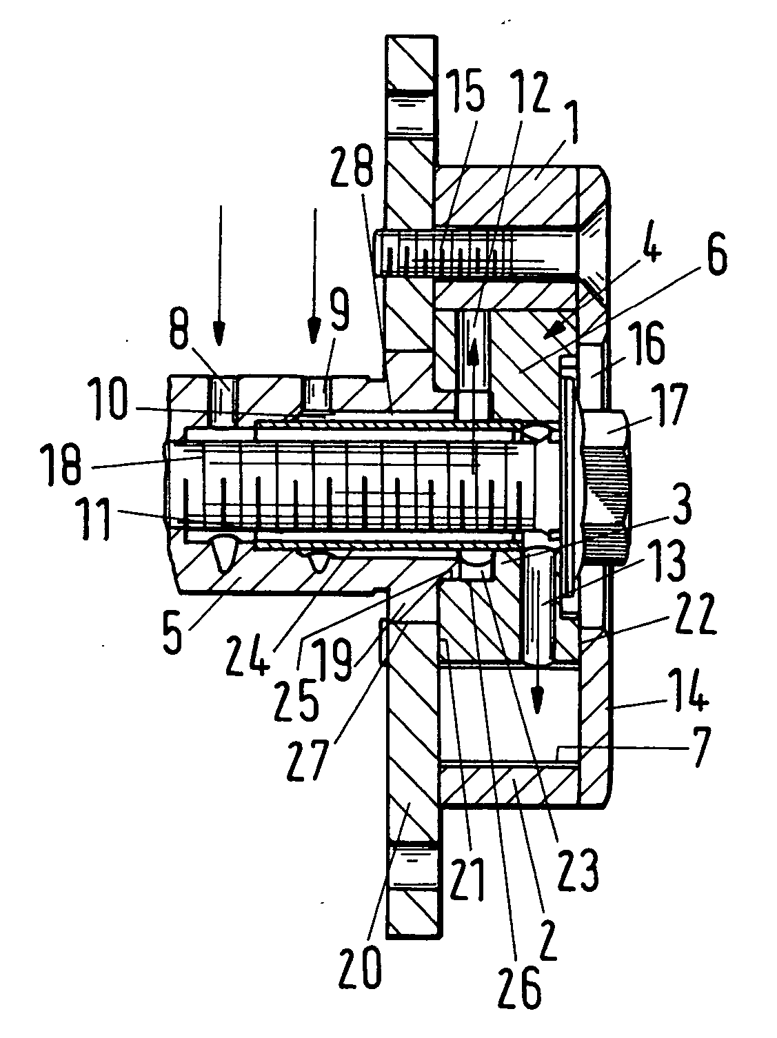
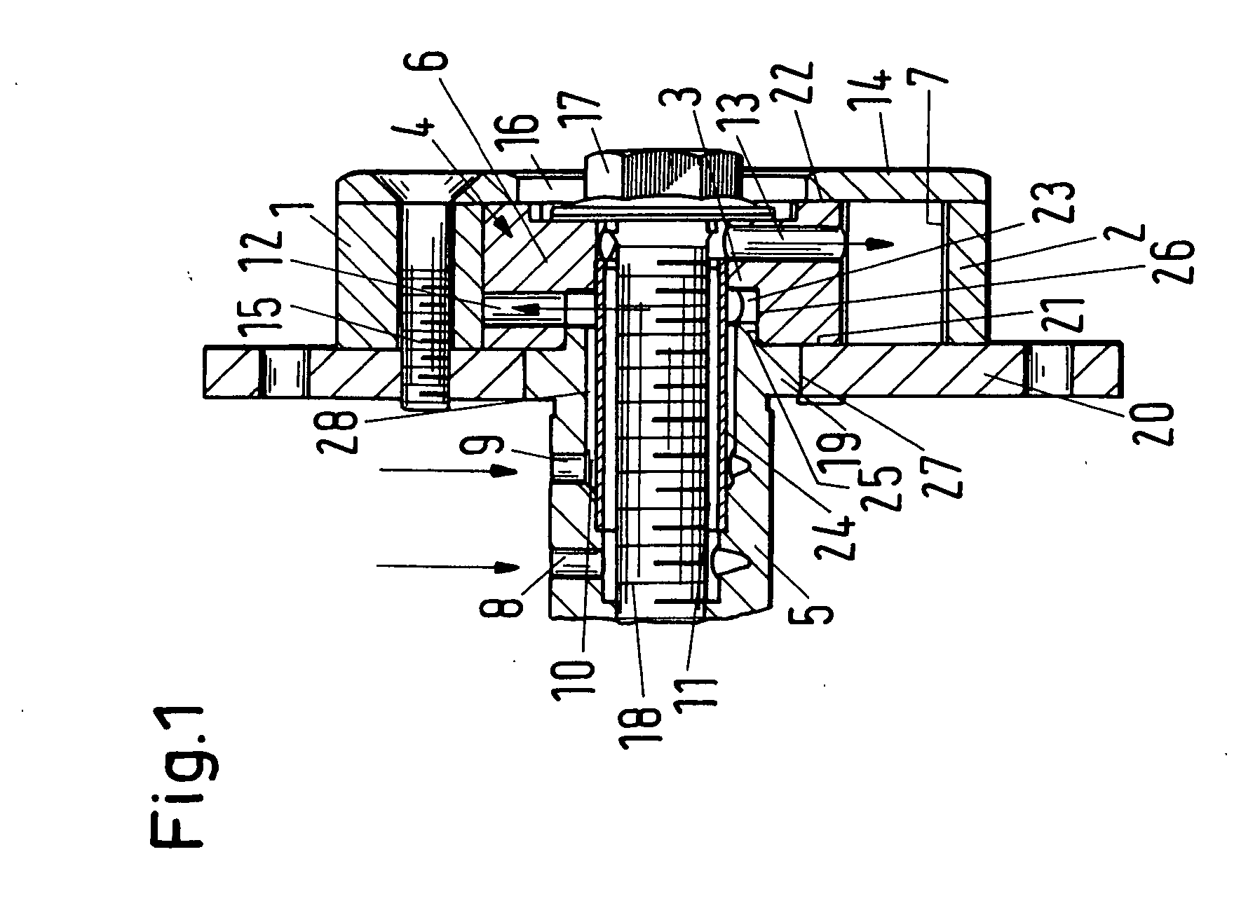
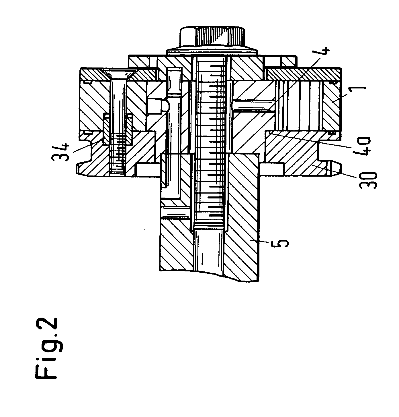
[0019] The adjusting device described herein is a camshaft adjuster with which, as is known in the art, a camshaft of an internal combustion engine of a motor vehicle can be adjusted. Since the configuration of such an adjusting device is known in the art, it will be explained only briefly in the following. It comprises a stator 1 having a cylindrical peripheral wall 2 and stays (not illustrated) projecting radially inwardly from the wall 2. Pressure chambers are formed between the stays. The stays are positioned with their end faces sealingly against the base member 3 of a rotor 4 that is fixedly attached to the camshaft 5. Radial vanes 6 project from the rotor base member 3 and rest sealingly with their end faces against the inner wall 7 of the peripheral stator wall 2. In each one of the pressure chambers of the stator 1, one vane is positioned whose width is smaller than the spacing betw...


PUM


Abstract

A device for adjusting a camshaft of an internal combustion engine of a motor vehicle has a stator and a rotor fixedly connected to a camshaft and rotatable relative to the stator. A drive wheel is fixedly connected to the stator and is centered by the camshaft. The stator has a peripheral area provided with a centering element interacting with a counter element provided on the drive wheel for aligning the drive wheel in a rotational direction relative to the stator.

Description

BACKGROUND OF INVENTION [0001] 1. Field of the Invention [0002] The invention relates to a device for adjusting a camshaft of an internal combustion engine of a motor vehicle, wherein the device comprises a stator and a rotor that is rotatable relative to the stator and is connected fixedly to the camshaft. At least one drive wheel is provided that is fixedly connected to the rotor. [0003] 2. Description of the Related Art [0004] A known adjusting device (FIG. 2) comprises a stator 1 surrounding a rotor 4. The rotor 4 is fixedly connected to a camshaft 5 so as to rotate with the camshaft. Moreover, a drive wheel 30 that is embodied as a chain wheel is mounted on the rotor 4. The rotor 4 has a collar 4a for receiving the drive wheel 30. This collar 4a projects axially past the end face of the rotor. The manufacture of the collar 4a is complex and expensive because it must be produced by turning. For aligning the drive wheel 30 relative to the stator 1, centering or positioning elemen...

Claims


Application Information

Patent Timeline
IPC IPC(8): F01L1/053F01L1/26F01L1/344
CPCF01L1/022F01L1/024F01L1/026F01L1/053F01L1/26Y10T74/2102F01L2101/00F01L2103/00F01L2103/01Y10T74/2101Y10T29/49293F01L1/3442F01L2303/01F01L2303/00F01L2301/00
Inventor NAUMANN, RALFSLUKA, GEROLDKNECHT, ANDREAS
Owner HYDRAULIK RING
Why Eureka
Try Eureka