Splice construction for elongate sections

Active Publication Date: 2005-01-20
SEMPERIT OSTE AMERIKANISCHE GUMMIWERKE AG
View PDF0 Cites 14 Cited by
  • Summary
  • Abstract
  • Description
  • Claims
  • Application Information

AI Technical Summary

Benefits of technology

[0033] In another embodiment of the method, the insert piece constitutes the reinforcing layer, in particular by cutting off an end piece thereof, which imparts to the endless belt-shaped tension element a higher capacity to withstand stress because the warp threads of the reinforcing layer and the insert piece also subtend the angle α, which reduces the stocks needed for manufacturing the tension element because additional components for the reinforcing layer can be dispensed with.
[0034] The fact that the ends of the reinforcing layer are bonded and/or stitched and/or welded and/or fused and/or clamped to the insert piece is also of

Problems solved by technology

In this connection, taking an open section with a C-shaped cross section as mentioned above, it is evide

Method used


Image

  • Splice construction for elongate sections
  • Splice construction for elongate sections
  • Splice construction for elongate sections

Examples


Example

[0040] Firstly, it should be pointed out that the same parts described in the different embodiments are denoted by the same reference numbers and the same component names and the disclosures made throughout the description can be transposed in terms of meaning to same parts bearing the same reference numbers or same component names. Furthermore, the positions chosen for the purposes of the description, such as top, bottom, side, etc., relate to the drawing specifically being described and can be transposed in terms of meaning to a new position when another position is being described. Individual features or combinations of features from the different embodiments illustrated and described may be construed as independent inventive solutions or solutions proposed by the invention in their own right.

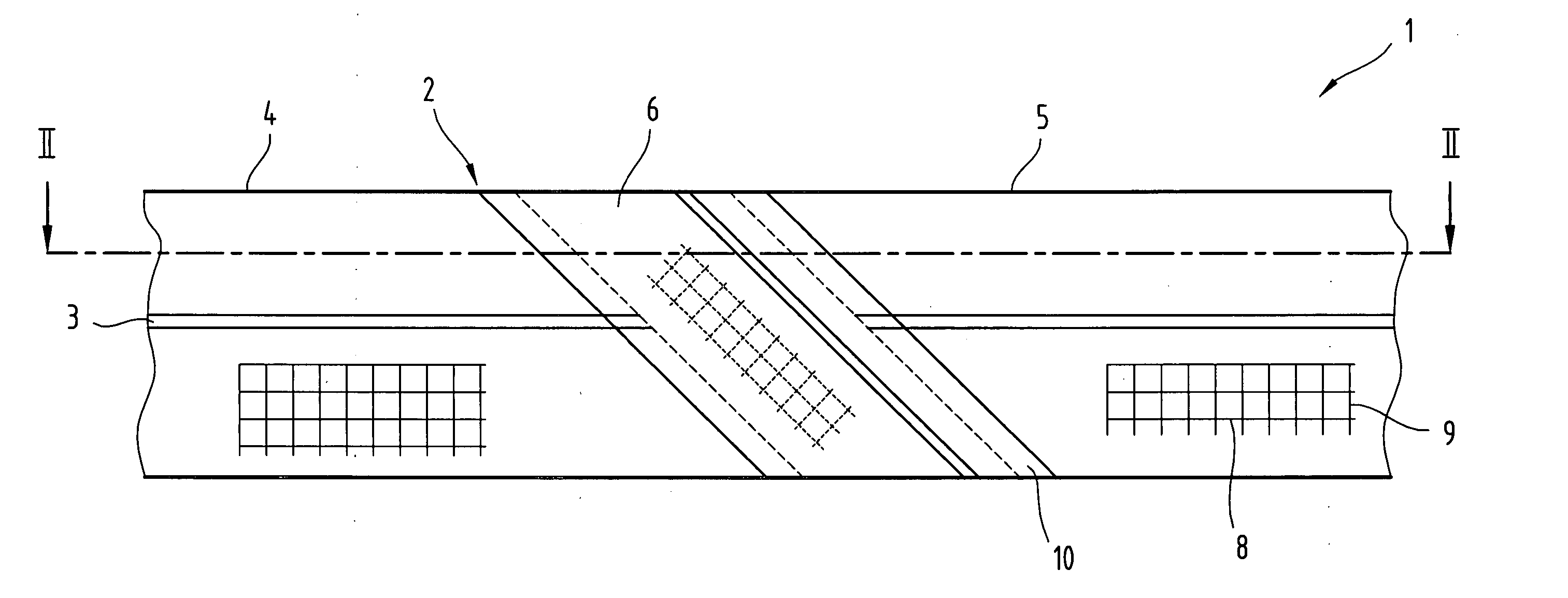
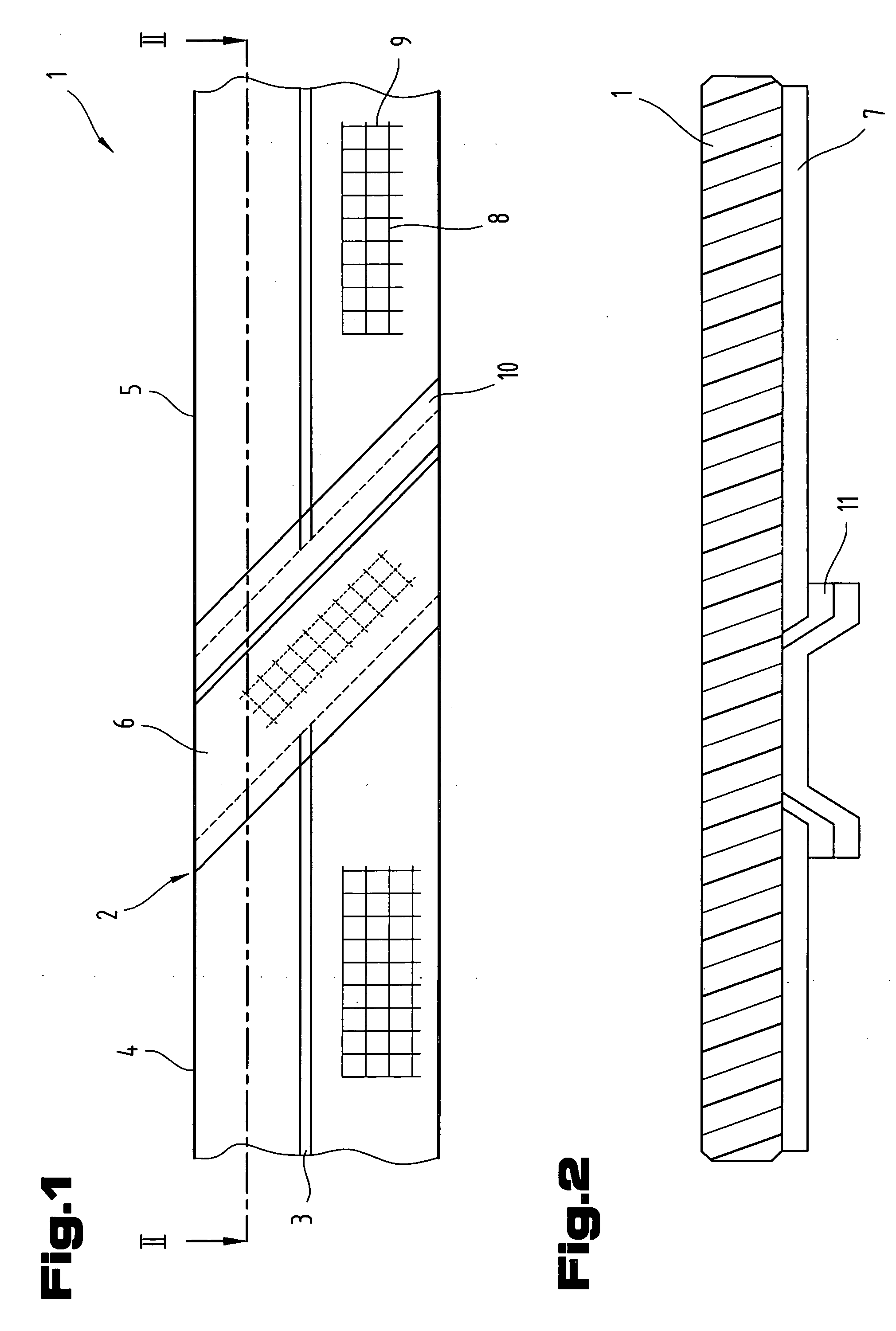
[0041]FIG. 1 illustrates a length of an endless belt-shaped tension element 1, providing a schematic detailed view of the joining point 2 between the two ends of the tension element 1.

[004...


PUM

PropertyMeasurementUnit
Angleaaaaaaaaaa
Angleaaaaaaaaaa
Angleaaaaaaaaaa

Abstract

The invention relates to an endless, belt-shaped tension element (1) for a conveyor system with at least one joining point (2) comprising an elastomer, in particular a cross-linked and/or thermoplastic elastomer, at least one reinforcing layer and optionally at least one tension support (3), two ends of the at least one reinforcing layer being disposed at the at least one joining point (2). An insert piece (6) is disposed between the two ends at the joining point (2), subtending an angle α with the tension element longitudinal extension, and the ends of the at least one reinforcing layer overlap with the insert piece (6).

Description

BACKGROUND OF THE INVENTION CROSS-REFERENCE TO RELATED APPLICATION [0001] The present application claims priority under 35 U.S.C. 119 of Austrian Application No. A 825 / 2003 filed May 28, 2003, the disclosure of which is incorporated by reference herein in its entirety. [0002] 1. Field of the Invention [0003] The invention relates to an endless, belt-shaped tension element for a conveyor system with at least one joining point, comprising an elastomer, in particular a cross-linked and / or thermoplastic elastomer, at least one reinforcing layer and optionally at least one tension support, two ends of the at least one reinforcing layer being disposed at the at least one joining point, a conveyor system with a circulating, endless, belt-shaped tension element and a drive system actively connected to the tension element, as well as a method of manufacturing an endless, belt-shaped tension element whereby a tension element section is made from an elastomer, a reinforcing layer is placed in ...

Claims


Application Information

Patent Timeline
IPC IPC(8): B29C65/00B29C65/50B29C65/62B29D29/06B66B23/24F16G3/10
CPCB29C65/5042B29C65/5028B29C66/1142B29C66/43129B29C66/5241B29C66/61B29D29/06B29K2021/00B29K2105/0836B29K2105/0845B29K2277/10B29K2305/12B29L2031/003B29L2031/709B66B23/24F16G3/10B29C65/62B29C65/5014B29C65/00B29C66/7212B29C66/7392B29C66/72141B29C66/71B29C66/1162B29K2277/00B29K2267/00B29K2311/00B29K2021/003B29C65/50
Inventor DURRER, ALBRECHTIMNITZER, JOHANN
Owner SEMPERIT OSTE AMERIKANISCHE GUMMIWERKE AG
Why Eureka
Try Eureka