
Article identification and tracking using electronic shadows created by RFID tags

a technology of electronic shadows and tags, applied in the field of radio frequency identification (rfid) technology, can solve the problems of inconvenience for shoppers, high cost of anchoring merchandise, and difficulty for shoppers to examine items and try on clothes, so as to facilitate the identification and tracking of items and foster marketing and merchandising effectiveness

Inactive Publication Date: 2005-01-20
CHECKPOINT SYST INC
View PDF4 Cites 167 Cited by
  • Summary
  • Abstract
  • Description
  • Claims
  • Application Information

AI Technical Summary

Benefits of technology

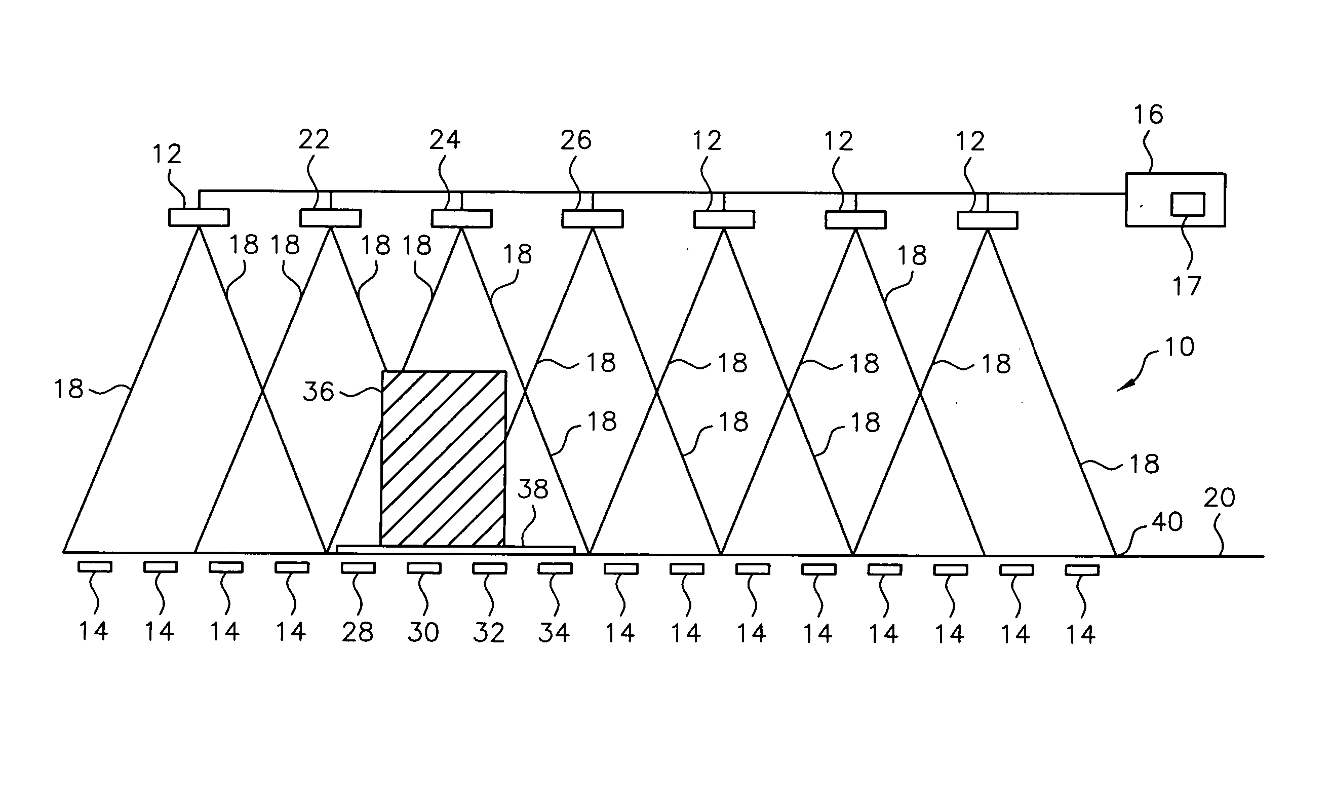
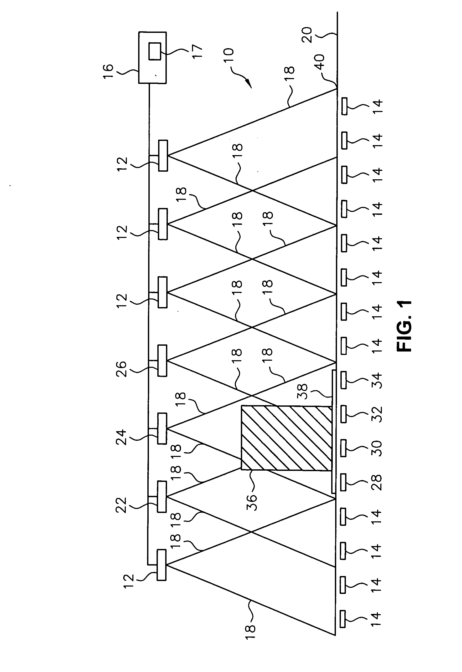
[0007] The preferred embodiments of the present invention specifically relate to the fields of security, RFID, marketing and retail. Other embodiments of the present invention may be applied to applications such as warehousing and distribution systems, manufacturing floor environments and people counting. The present invention uses passive RFID (radio frequency identification) tag technology to facilitate the identification and tracking of items in an environment through a technique known as shadowing. One approach of this invention uses this shadow technique to perform functions such as theft (shrink) deterrence / detection; tracking the motion of objects through an environment by monitoring the shadow; and correlation analysis of people shadows to tagged items (e.g., merchandise, articles) to foster marketing and merchandising effectiveness.
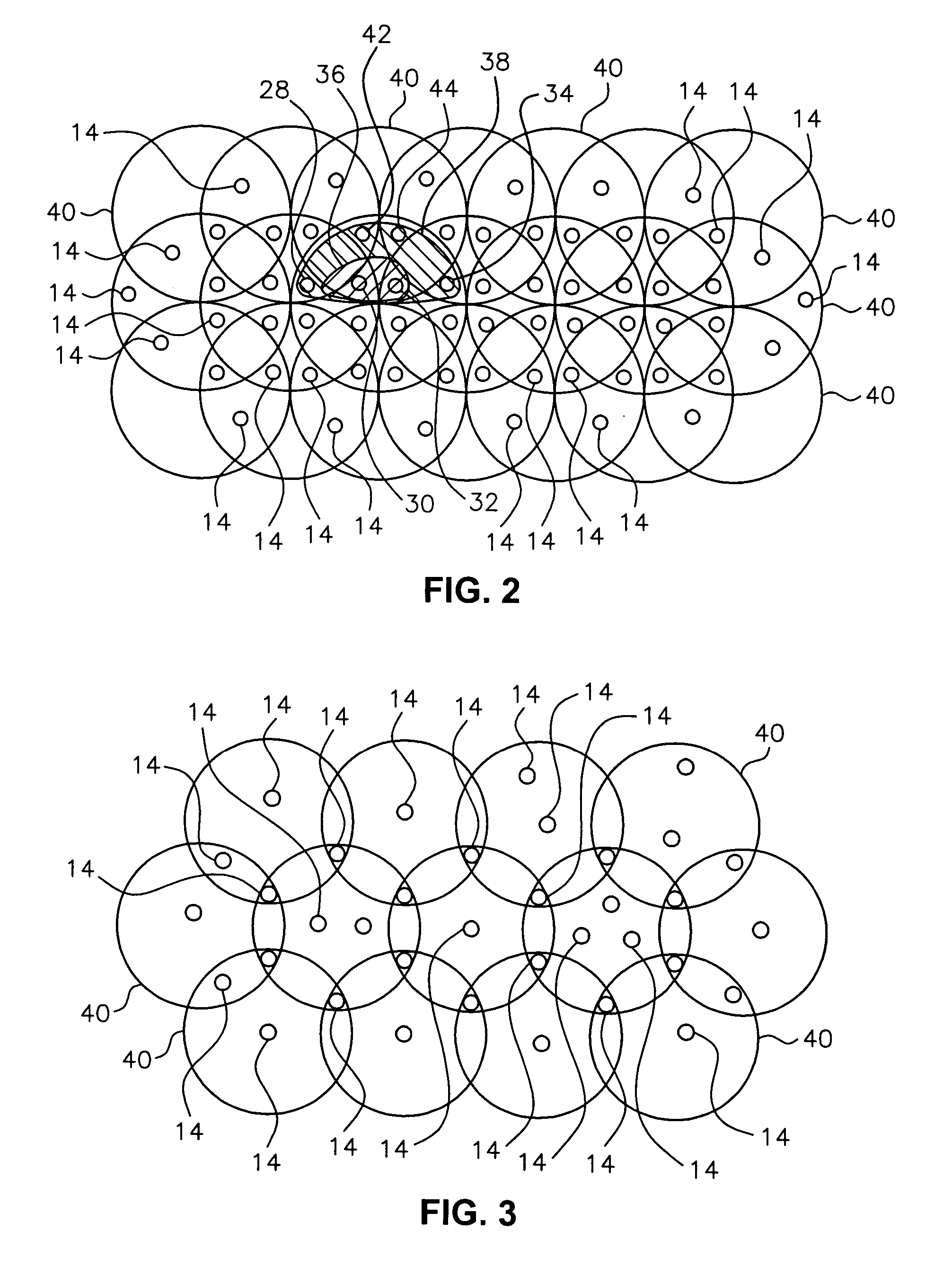
[0011] The term shadow or electronic shadow as defined in the preferred embodiments herein refers to the absence of detection for a known RFID sensor. As an object or target moves within a pre-described sensor net environment of a volumetric security or detection zone with communicating antenna and RFID sensors, the object or target blocks the line of sight between respective antenna and sensors, preventing electromagnetic coupling between the sensor and the antenna and thus casting an electromagnetic shadow along the line of sight. For example, a person walking over a floor mounted sensor blocks the detection of the RFID sensor, thereby creating an electronic shadow. That is, the person standing above an RFID sensor will cause signal absorption, reflection and attenuation, which prevents a read of the RFID sensor by an associated antenna. The series of electronic shadows (the real time sequence of electronic shadows) can identify the vector movement of people within a volumetric detection zone.

Problems solved by technology

Anchoring the merchandise in place makes it difficult for shoppers to examine items and try on garments.
This inconvenience motivates shoppers to shop at stores where the merchandise is more accessible.
In addition, anchoring merchandise is costly as a store must provide labor just to release the merchandise.
However, the cost of labor is expensive and the surveillance systems can be intrusive, especially in areas (e.g. dressing rooms) where shoppers would prefer some level of privacy.
EAS systems are limited by the capabilities of their tags.
Unfortunately, EAS tags contain no information.
Unfortunately, RFID systems encounter problems of obstruction or improper disorientation.
The person hiding the tag can walk through the RFID system's detection zones without sounding an alarm and the system has no way to locate the loss tag or its associated article.
If a RFID tag is hidden, it can not be identified or tracked with known tagging systems.
However, this approach is expensive and invasive.
However, neither of these approaches has solved the need to non-invasively identify and track moving objects.

Method used


Image

  • Article identification and tracking using electronic shadows created by RFID tags
  • Article identification and tracking using electronic shadows created by RFID tags
  • Article identification and tracking using electronic shadows created by RFID tags

Examples


example 1

[0044] Loss Prevention—Electronic mapping and electronic shadows may be used to determine the vector motion / direction (e.g. towards the exit of the store or towards the point of sale—cash register) and velocity (speed) of a customer in a retail store. By combining this information with the knowledge of a product in the possession of the customer (e.g., exact type, quantity, value), it may be determined if the product is likely being stolen. In particular, motion of a shadow with non-purchased goods towards an exit may indicate an attempted theft, especially if the shadow / tag does not go past a point-of-sale. This sequence of information and events could signal a store employee to approach the customer before exiting the store and thereby prevent a likely shoplifting event. The preferred tracking system of the invention can also detect theft upon a sudden loss of a tagged product (e.g., foil-lined bag, baby carriage, shopping bag, removed tag) in association with a shadow. In this si...

example 2

[0045] Cross Merchandising (e.g., complementary product selections)—By using the same information as in Example 1 (e.g., vector / motion direction of customer and the knowledge of the products in hand by the customer), if the customer's vector direction is the point of sale cash register, this knowledge and information can be used to automatically display to the customer (via a well-known display system in the queue for checkout) or to prompt a sales employee to suggest an array of complimentary products that match the customer-selected items. As another demonstration of cross merchandising, when a customer, identified as a shadow, enters a dressing room, the tracking system in accordance with the preferred embodiments can advertise goods associated with the tagged merchandise brought into the dressing room with the customer on a well-known display device located in the dressing room. The computer program in accordance with the invention can match the merchandise brought into the dres...

example 3

[0046] Customer flow / plan-a-gram / in store marketing—Based on the electronic shadow of customers and the reference map of fixed RFID sensors on stationary store fixtures and / or in the floor, a trend analysis can be established to understand customer flow. This trend analysis can allow merchandising to optimize customer flow within the store.

[0047] This same scenario, along with the markdown racks and / or store marketing, can also establish trend analysis to optimize messaging and markdown locations within the retail environment. By combining this information with the knowledge of the products in the hand or before a customer, trend analysis can also be established based on, for example, the amount of time the customer considers a product and the percentage of times that the customer purchases considered products.

[0048] The correct products in the correct locations can improve sales throughput. The ability to electronically verify exact product and type can be used to monitor invento...


PUM


Abstract

A tracking system uses RFID (radio frequency identification) tag technology to facilitate the identification and tracking of items in an environment through a technique known as shadowing. As an object or target moves within a pre-described detection zone with communicating antenna and RFID sensors, the object or target blocks the line of sight between respective antenna and sensors, preventing electromagnetic coupling between the sensor and the antenna and thus casting an electromagnetic shadow along the line of sight. One approach of this invention uses this shadow technique to perform functions such as theft (shrink) deterrence / detection; tracking the motion of objects through an environment by monitoring the shadow; and correlation analysis of people shadows to tagged items (e.g., merchandise, articles) to foster marketing and merchandising effectiveness.

Description

CROSS-REFERENCE TO RELATED APPLICATIONS [0001] This application is a Nonprovisional of U.S. Provisional Application Ser. No. 60 / 471,885 filed May 19, 2003, and entitled “Article Identification and Tracking using Electronic Shadows Created by RFID Tags.”FIELD OF INVENTION [0002] This invention relates to radio frequency identification (RFID) technology and, in particular, to RFID security systems having the capability to non-invasively detect and track an object within a security zone based on a loss of information. BACKGROUND OF THE INVENTION [0003] Retailers focusing on loss prevention (e.g. theft) traditionally have three approaches to minimize loss: (1) anchoring the merchandise in place (e.g., attaching cables to the merchandise, putting articles in display cases and behind the counter); (2) using video surveillance systems and / or security guards to watch everyone in the store; and (3) using an alarm system with special tags attached to items that sounds off an alarm whenever a ...

Claims


Application Information

Patent Timeline
IPC IPC(8): G06K7/00G06K7/08G06K17/00G07C9/00
CPCG06K7/0008G06K7/10079G08B13/2462G06K2017/0045G07C9/00111G06K7/10336G07C9/28
Inventor ECKSTEIN, ERICMAZOKI, GARY T.RICHIE, WILLIAM S. JR.
Owner CHECKPOINT SYST INC
Learn More