Liquid crystal display device and manufacturing method thereof

a liquid crystal display and manufacturing method technology, applied in non-linear optics, instruments, optics, etc., can solve the problems of defective display generation, difficult control of the above-mentioned recessed shape, and degraded display quality, so as to prevent the generation of displacement between the upper and lower substrates, improve the display quality, and enhance the frictional force

Active Publication Date: 2005-01-20
PANASONIC LIQUID CRYSTAL DISPLAY CO LTD +1
View PDF2 Cites 20 Cited by
  • Summary
  • Abstract
  • Description
  • Claims
  • Application Information

AI Technical Summary

Benefits of technology

[0020] Accordingly, the present invention has been made to overcome the above-mentioned drawbacks, and it is an object of the present invention to provide a liquid crystal display device and a method of manufacture thereof which can result in a high-quality image display, wherein by enhancing the frictional force between columnar spacers and a counter substrate, and keeping the gap between the substrates uniform, the generation of a displacement between upper and lower substrates is prevented.
[0021] To achieve such an object, in a liquid crystal display device according to the present invention, support column surfaces of columnar spacers are made rough so as to increase the frictional force between the color filter substrate and the thin film transistor substrate, which substrates are arranged to face each other in an opposed manner, thus preventing a displacement between the color filter substrate and the thin film transistor substrate attributed to stress applied to the columnar spacers due to warping, deflection and the like of the color filter substrate and the thin film transistor substrate.

Problems solved by technology

However, a liquid crystal display device having such a constitution has a drawback in that the formation of the recessed portions on the peak portions of the columnar spacers in a recessed form is liable to be subject to the influence of a wraparound of light from an edge of the mask at the time of exposure, the flow direction of a developing solution and the like at the time of developing, and, hence, the controllability of the above-mentioned recessed shape is difficult.
Further, since the peak portions of the columnar spacers are formed in a recessed shape, the liquid crystal is not filled in the peak portions and cavities are formed, and, hence, the peak portions are observed with the naked eye as if air bubbles are generated in the peak portions, thus giving rise to a drawback that the display quality is degraded.
Further, the support column surfaces of the columnar spacers, particularly portions of the columnar spacers which come into contact with the counter substrate, are formed to have a smooth shape, so that a displacement of the substrates is generated due to warping or deflection of the opposing upper and lower substrates, thus giving rise to a drawback that a defective display is liable to be generated.

Method used


Image

  • Liquid crystal display device and manufacturing method thereof
  • Liquid crystal display device and manufacturing method thereof
  • Liquid crystal display device and manufacturing method thereof

Examples


Embodiment Construction

[0029] Hereinafter, a mode for carrying out the present invention will be explained in detail in conjunction with the drawings.

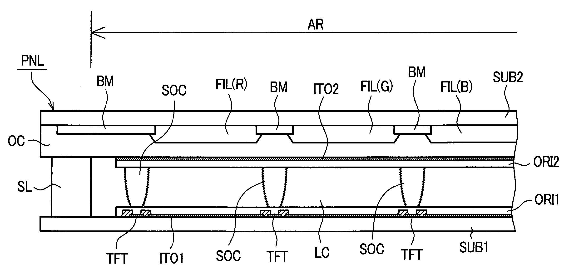
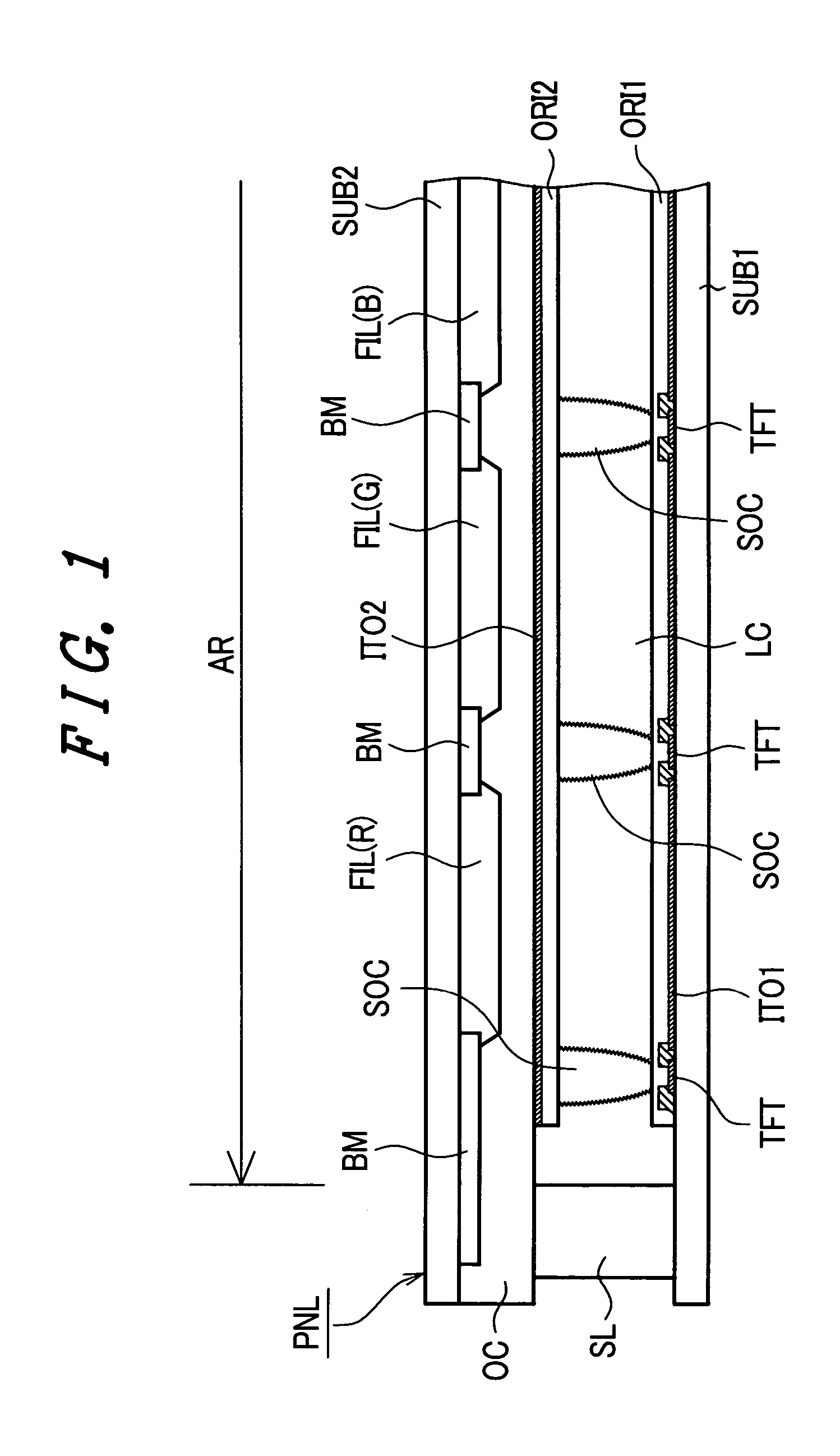
[0030]FIG. 1 is a cross-sectional view showing the constitution of the liquid crystal display device according to one embodiment of the present invention. In FIG. 1, a first substrate SUB1 constitutes a thin film transistor substrate and a second substrate SUB2 constitutes a color filter substrate. On an inner surface of the thin film transistor substrate SUB1, a large number of thin film transistors TFT and the like are arranged two-dimensionally corresponding to the number of pixels.

[0031] Each thin film transistor TFT includes, although not shown in the drawing, a gate electrode, a semiconductor layer formed of amorphous silicon or poly silicon, a source electrode and a drain electrode. Further, on the inner surface of the thin film transistor substrate SUB1, pixel electrodes ITO1 are formed of a transparent conductive film and are connected to the sour...


PUM

PropertyMeasurementUnit
depthaaaaaaaaaa
colorsaaaaaaaaaa
electric fieldsaaaaaaaaaa

Abstract

In a liquid crystal display device having a pair of substrates that are opposite to and bonded to each other, a liquid crystal layer is sealed between the pair of substrates, and columnar spacers are formed on one of the pair of substrates and in contact with the other substrate to maintain a gap between the pair of substrates. The surfaces of support columns of the columnar spacers are made to be rough to enhance the friction force between the pair of substrates and to prevent the other of the pair of substrates from diverging from the one of the pair of substrates, so that display quality of the liquid crystal display device is improved.

Description

[0001] The present application claims priority from Japanese application JP 2003-196409 filed on Jul. 14, 2003, the content of which is hereby incorporated by reference into this application. BACKGROUND OF THE INVENTION [0002] The present invention relates to a liquid crystal display device and to a method of manufacture thereof; and, more particularly, the invention relates to a liquid crystal display device which includes spacers for holding a fixed gap between a pair of substrates, which seal a liquid crystal layer therebetween, the spacers being constructed to decrease display irregularities, thus enabling an image display of high quality, and to a method of manufacture thereof. [0003] As an example of display devices which are capable of producing a color display of high definition for notebook type computers and computer monitors, liquid crystal display devices have been popularly adopted. This type of liquid crystal display device is basically configured such that a liquid cr...

Claims


Application Information

Patent Timeline
Patent Type & Authority Applications(United States)
IPC IPC(8): G02F1/1339
CPCG02F1/13394
Inventor ISHII, AKIRAIMABAYASHI, YOSHITAKA
Owner PANASONIC LIQUID CRYSTAL DISPLAY CO LTD
Why Eureka
Try Eureka