Composite micro-structured sheet for diffusing and condensing light

Inactive Publication Date: 2005-01-20
IND TECH RES INST
View PDF8 Cites 11 Cited by
  • Summary
  • Abstract
  • Description
  • Claims
  • Application Information

AI Technical Summary

Benefits of technology

[0006] The object of the present invention is to provide a composite micro-structured sheet for diffusing and condensing light so that the shadows or line defects of an LCD screen are prevent

Problems solved by technology

Wherever the light sources are located, the profile of the light source easily causes a non-uniformity of brightness, shadows, or line defects to the displaying image.
However, the illuminating light will be absorbed when passing through

Method used


Image

  • Composite micro-structured sheet for diffusing and condensing light
  • Composite micro-structured sheet for diffusing and condensing light
  • Composite micro-structured sheet for diffusing and condensing light

Examples


Example

EXAMPLE 1

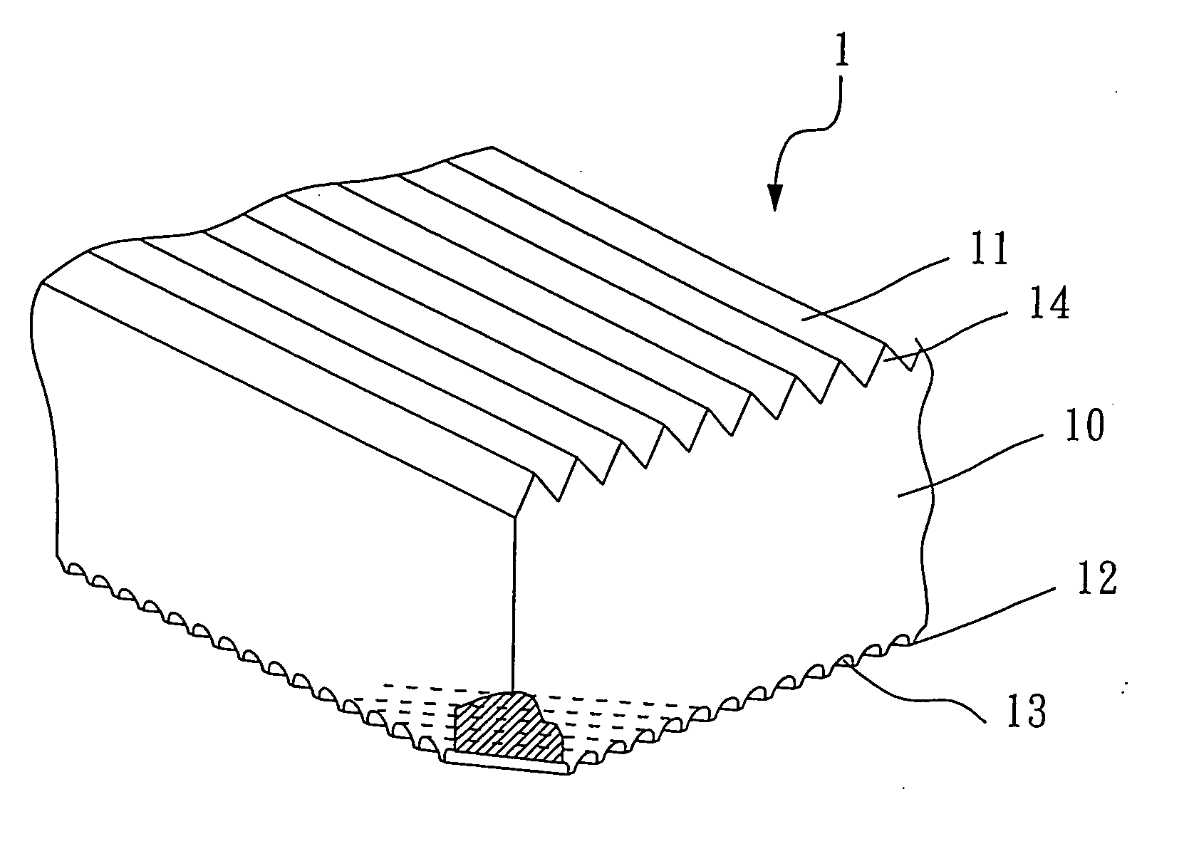
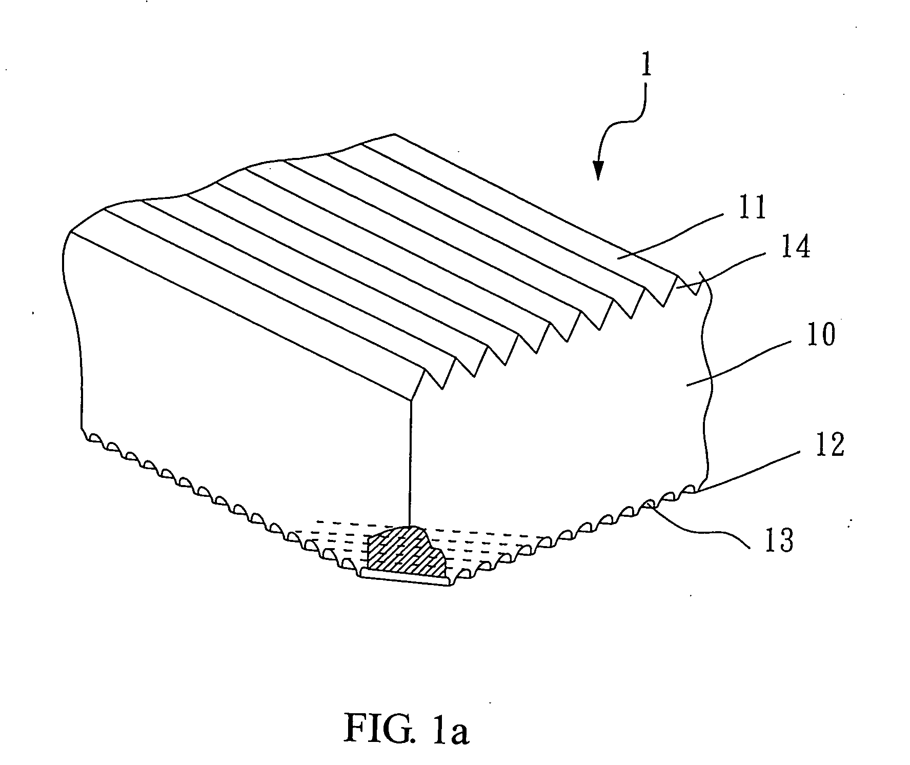
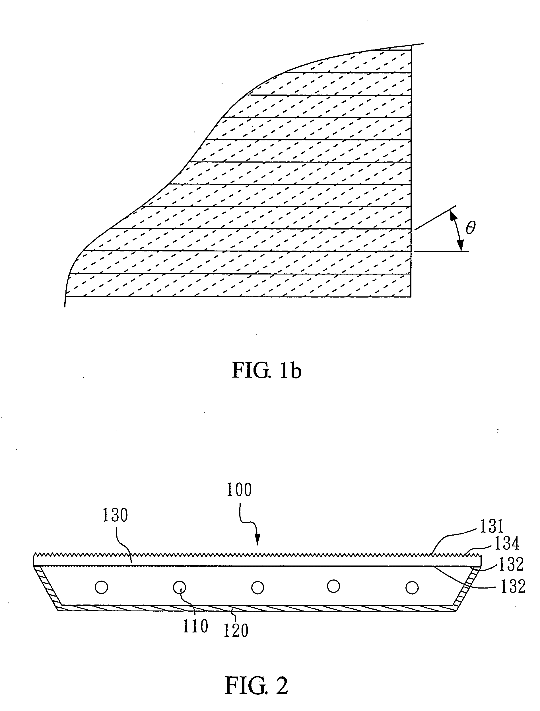
[0016] With reference to FIG. 1a, there is shown a perspective view of a preferred embodiment of the composite micro-structured sheet of the present invention. The composite micro-structured sheet 1 is composed of the PMMA substrate 10 having a top surface 11 and a bottom surface 12. On the bottom surface 12, there is formed a plurality of straight trenches 13 that are parallel to each other and constructed of concave pillar lenses, and have an arc cross-section for diffusing the incident light on the bottom surface 12. On the top surface 11, there is formed a plurality of rhombus protrusions 14 for raising the semi-brightness angle of the light that has passed through the bottom surface 12. The rhombus protrusions 14 intersect the straight trenches 13 and the included angle θ therebetween is 30 degrees, as shown in FIG. 1b.

Example

EXAMPLE 2

[0017] With reference to FIG. 2, there is shown a perspective view of another preferred embodiment of the directly-under-light backlight module of the present invention. The backlight module 100 includes a light source 110, a reflective housing 120, and a composite micro-structured sheet 130. The light source 110 is a cold cathode fluorescent lamp for providing the illuminating light. The reflective housing 120 is adjacent to the light source 110 for receiving the light source 110 and reflecting the illuminating light from the light source 110. The reflective housing 120 is optionally made by stamping or by extrusion. Preferably, the inner surface of the reflective housing 120 is coated with a reflecting and diffusing material for enhancing the reflecting efficiency. The composite micro-structured sheet 130 is the same with the composite micro-structured sheet 1 of Example 1. The composite micro-structured sheet 130 having a top surface 131 and a bottom surface 132 is abov...

Example

EXAMPLE 3

[0019] The construction of the present example is very similar to that of Example 2, except that on the bottom surface of the composite micro-structured sheet there is formed a micro-lens array, which is constructed of hexagonal convex lenses that are very close to each other. The simulation result is shown in FIG. 5, which reveals that the composite micro-structured sheet of the present example improves the light uniformity from the backlight module up to 80%.

[0020] Traditionally, the backlight module needs 4 or 5 optical sheets to uniformly disperse and condense the illuminating light emitting from the light source. However, those optical sheets are too expensive to reduce the manufacturing cost of the backlight module. The present invention replaces the light diffusing sheet and the prism of the backlight module with a composite micro-structured sheet. Taking advantage of the microstructures, the composite micro-structured sheet has both functions of light diffusing an...


PUM


Abstract

A composite micro-structured sheet for diffusing and condensing light is disclosed, which includes a substrate having a top surface and a bottom surface, wherein a plurality of straight trenches with an arc cross-section or an micro-lens array is formed on the bottom surface for diffusing the incident light on the bottom surface, and a plurality of rhombus protrusions is formed on the top surface for raising the semi-brightness angle of the light that has passed through the bottom surface.

Description

BACKGROUND OF THE INVENTION [0001] 1. Field of the Invention [0002] The present invention relates to a composite micro-structured sheet for diffusing and condensing light and, more particularly, to a micro-structured sheet having the complex functions of diffusing and condensing light used in a backlight module of a liquid crystal display. [0003] 2. Description of Related Art [0004] Currently, there are two types of lighting module for a flat panel display. One is the back type, and the other is the front type. The backlight module is further classified as a side-light (edge-light) type and a directly-under-light (bottom light) type according to their locations of light sources. Wherever the light sources are located, the profile of the light source easily causes a non-uniformity of brightness, shadows, or line defects to the displaying image. Generally, at least one light-diffusing sheet and at least one light-condensing sheet are used for uniformly diffusing the illuminating light...

Claims


Application Information

Patent Timeline
IPC IPC(8): G02B3/00G02B5/02
CPCG02B3/005G02B3/0056G02B5/045G02B5/0278G02B5/0215
Inventor PAN, I-KAIYAU, PO-HUNGLIN, JAIN-SHPAO, YU-NAN
Owner IND TECH RES INST
Why Eureka
Try Eureka