Glare blocking device

a technology glare reduction, which is applied in the field of glare blocking device, can solve the problems of affecting various types of optical systems, impairing driving effectiveness, and essentially unable to see the road ahead, so as to reduce the intensity of incident light rays, and automatically reduce the glare produced in the spatial scene

Inactive Publication Date: 2005-01-20
FARIS SADEG M
View PDF3 Cites 5 Cited by
  • Summary
  • Abstract
  • Description
  • Claims
  • Application Information

AI Technical Summary

Benefits of technology

[0009] The present invention provides an apparatus for automatically reducing glare produced from a spatial scene by reducing the intensity of light rays propagating from points in the three-dimensional spatial scene towards an optical element having a field of view. The apparatus includes an electro-optical element having an optically transparent surface including a plurality of electrically addressable pixels through which the field of view of the optical element passes. Each pixel has a controllable light transmittance for selectively reducing the intensity of incident light rays propagating from one or more points in the spatial scene, through the pixel, then towards the optical element. The apparatus also includes an image acquisition device for acquiring one or more images of the spatial scene within the field of view of the optical element. A processor is also provided for processing the one or more acquired images and determining at which pixels the light transmittance is to be actively controlled in order to reduce the intensity of incident light rays by a selected amount before reaching the optical element. Further, a control is provided for actively controlling the light transmittance of the determined pixels so that after incident light rays propagate through the determined pixels, the incident light rays propagate towards the optical element with an intensity reduced by the selected amount, so that glare produced from the spatial scene is automatically reduced. To provide for convenient and portable operation of the apparatus, a power supply may be integrated within the apparatus for providing electrical power to the image acquisition device, the processor, and control.

Problems solved by technology

Many sources of illumination producing glare which detrimentally affects various types of optical systems.
This may be problematic, for example, in areas of shade, or, for example, while driving in the less illuminated areas such as trials.
This is particularly problematic when the headlamps are in high-beam mode, such that the driver is essentially unable to view the road ahead.
As a driver continues to view the intense headlamps, the driver's division becomes fatigued, consequently impairing their ability to drive effectively.

Method used


Image

  • Glare blocking device
  • Glare blocking device
  • Glare blocking device

Examples


Embodiment Construction

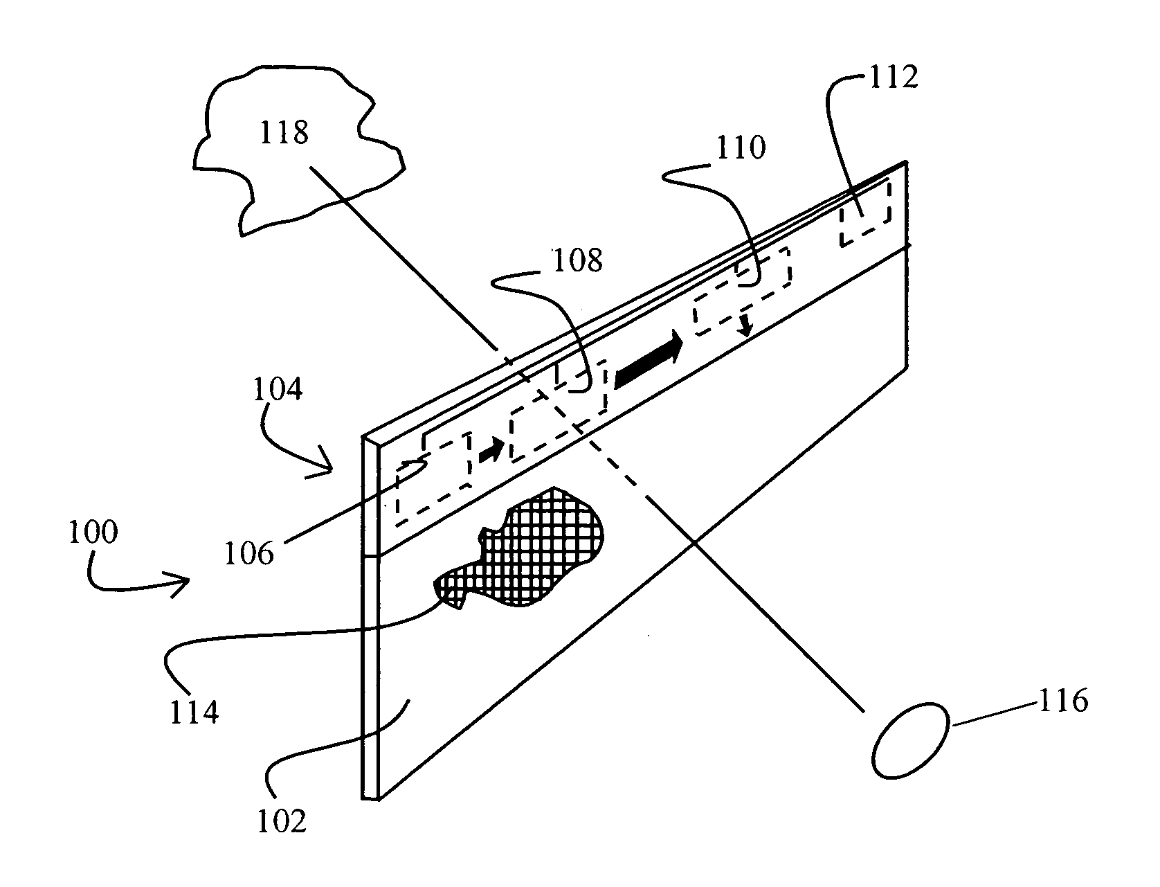
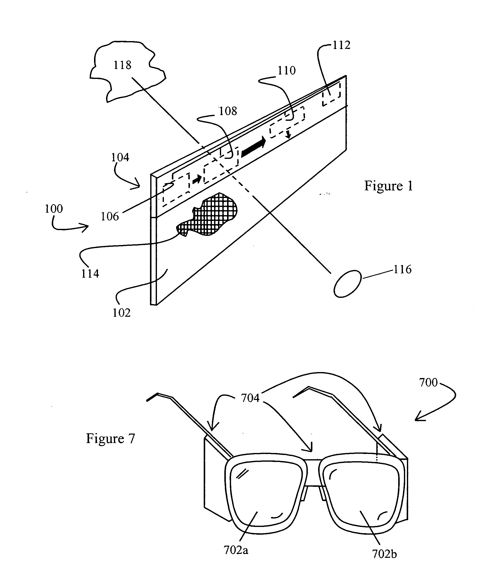
[0021] Referring now to FIG. 1, a general embodiment of a glare blocking device 100 is depicted. Glare blocking device 100 includes an electro-optical element 102 and a control and power system 104. The control and power system 104 includes therein an image acquisition device 106, a processor 108, a control 110, and a power supply 112. All of the components of the glare blocking device according to this embodiment are integrated into a wireless apparatus. This wireless apparatus conveniently may be employed in a variety of applications, including, but not limited to, automobile visors, glasses, masks, attachments (e.g., 40 camera), shades (e.g., as in on the side windows of automobile, such as to prevent glare and other excess illumination to passengers within the automobile), and the like.

[0022] The electro-optical element 102 comprises a plurality of pixels 114. During operation, an optical element 116 is in optical communication with an illumination source 118. If the illuminati...


PUM


Abstract

An apparatus is provided for automatically reducing glare produced from a spatial scene by reducing the intensity of light rays propagating from points in the three-dimensional spatial scene towards an optical element having a field of view. Further, an apparatus is provided that automatically reduces interfering illumination produced from an illumination source by reducing the intensity of light rays propagating from the illumination source towards a sensor having a field of view of radio communication. Both apparatus include an electro-optical element having an optically transparent surface including a plurality of pixels through which the field of view of the optical element or the sensor passes. Each pixel has a controllable light transmittance for selectively reducing the intensity of incident light rays propagating from one or more points from the illumination source, through the pixel, then towards the sensor or optical element. An image acquisition device is included for acquiring one or more images of the illumination source within the field of view of the sensor or optical element. A processor is also included for processing the acquired images and determining at which pixels the light transmittance is to be actively controlled in order to reduce the intensity of incident light rays before reaching the sensor or optical element. A control is also provided for actively controlling the light transmittance of the determined pixels so that after incident light rays propagate through the determined pixels, the incident light rays propagate towards the sensor or optical element with reduced intensity.

Description

RELATED APPLICATIONS [0001] The present invention claims priority to U.S. Provisional Patent Application Ser. No. 60 / 288,675 entitled “Glare Blocking Device” filed on May 7, 2001, which is hereby incorporated by reference in its entirety.BACKGROUND OF THE INVENTION [0002] 1. Field of the Invention [0003] The present invention generally relates to glare blocking device, and particularly to an integrated device that selectively reduces the intensity of incident light as is propagated toward an optical element. [0004] 2. Description of the Prior Art [0005] Many sources of illumination producing glare which detrimentally affects various types of optical systems. For example, many outdoor activities are effectuated more comfortably with the use of sunglasses, particularly in times of extreme sunlight. However, with use of conventional sunglasses, all visible light intensity is reduced. This may be problematic, for example, in areas of shade, or, for example, while driving in the less ill...

Claims


Application Information

Patent Timeline
Patent Type & Authority Applications(United States)
IPC IPC(8): A61F9/06B60J3/02G02C7/10
CPCA61F9/065G02C7/101B60J3/0208
Inventor FARIS, SADEG M.
Owner FARIS SADEG M
Why Eureka
Try Eureka