Constant velocity universal joint

a constant velocity, universal joint technology, applied in the direction of yielding couplings, rotary machine parts, couplings, etc., can solve the problems of increasing the amount of abrasion of the large inner diameter portion, affecting the nvh performance of the vehicle, and reducing the design freedom of the underbody of the vehicl

Active Publication Date: 2005-01-20
NTN CORP
View PDF4 Cites 4 Cited by
  • Summary
  • Abstract
  • Description
  • Claims
  • Application Information

AI Technical Summary

Benefits of technology

[0020] The roller assembly is interposed between the trunnion and the outer joint member so as to serve to transmit a torque. Since a transmission direction of a torque always perpendicularly crosses the axial line of the joint in this type of constant velocity universal joint, the torque can be transmitted if only the trunnion and the ring are in contact with each other in the transmission direction of the torque. Accordingly, the gaps between the trunnion and the ring in the axial direction of the joint do not bring about any inconveniences in torque transmission.

Problems solved by technology

Such a slide resistance and an induced thrust cause the vibration and noise of a vehicle body, affecting NVH performance of the vehicle to decrease the freedom of design of the underbody of a vehicle.
If the joint turns in such a state, sliding friction occurs at an interfered portion, which may sometimes increase the amount of abrasion of the large inner diameter portion 15.

Method used


Image

  • Constant velocity universal joint
  • Constant velocity universal joint
  • Constant velocity universal joint

Examples


Embodiment Construction

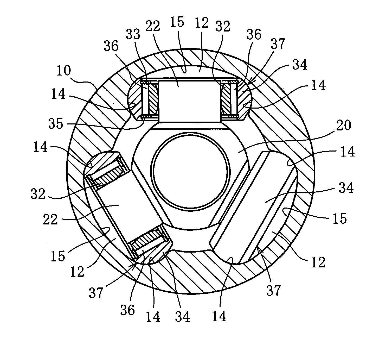
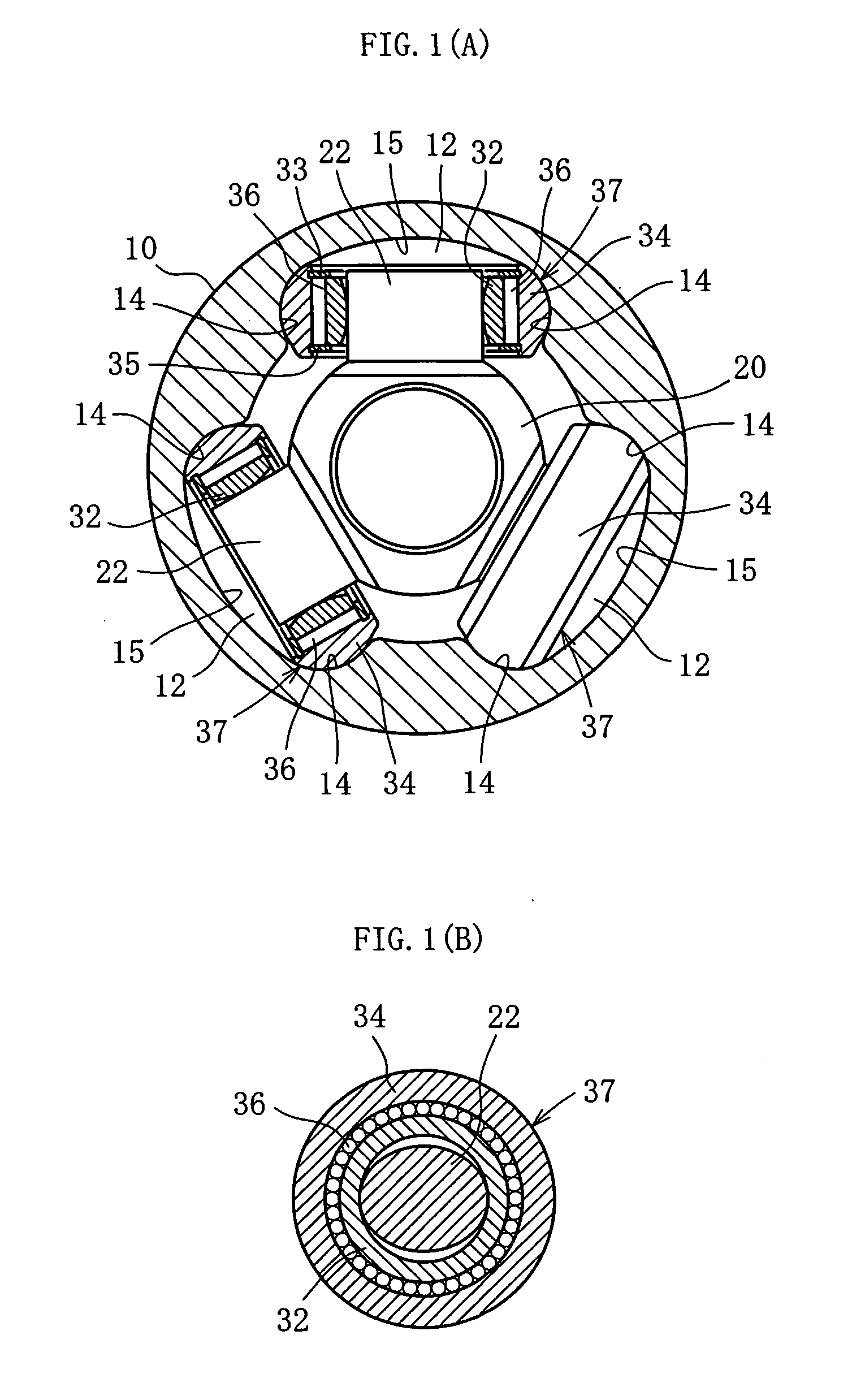
[0027] Hereinafter, preferred embodiments of a constant velocity universal joint according to the present invention will be described. FIG. 1(A) is a cross-sectional view showing a joint, and FIG. 1(B) is a cross-sectional view perpendicular to a trunnion. As shown in FIGS. 1(A) and 1(B), a constant velocity universal joint is composed of an outer joint member 10 and a tripod member 20. One of two shafts to be coupled is connected to the outer joint member 10, whereas the other shaft is connected to the tripod member 20.

[0028] The outer joint member 10 has three track grooves 12 extending in an axial direction on its inner circumferential face. Roller guiding faces 14 are formed on lateral walls of each of the track grooves 12, which face each other in a circumferential direction. The tripod member 20 has three trunnions 22 provided so as to protrude in a radial direction. A roller 34 is attached to each of the trunnions 22. The roller 34 is housed within each of the track grooves ...


PUM


Abstract

In a no-flange type outer joint member, the amount of abrasion in a large inner diameter portion formed for a track groove is intended to be restrained. In a tripod type constant velocity universal joint including: a no-flange type outer joint member; and a roller assembly including a roller, being attached to a trunnion so as to be capable of oscillating, hardened layers are formed on portions of a large inner diameter portion of the outer joint member, which are in contact with an inclined roller assembly. In this case, a value of F/D is set equal to or less than 0.45, where a distance from a center of the track groove of the outer joint member to the ends of both the hardened layers on the side of the center of the track groove is F, and a diameter of an outer circumference of the roller assembly is D.

Description

BACKGROUND OF THE INVENTION [0001] 1. Field of the Invention [0002] The present invention relates to a constant velocity universal joint, in particular, to a sliding type tripod constant velocity universal joint. [0003] 2. Description of the Related Art [0004] Generally, a constant velocity universal joint is a kind of universal joint, which couples a driving shaft and a driven shaft with each other and allows the transmission of torque at a constant velocity even if an angle is formed between the two shafts (not aligned straight). Among the constant velocity universal joints, a sliding type enables relative axial displacement between two shafts by plunging a joint. As one kind of the sliding type constant velocity universal joint, a tripod type constant velocity universal joint is widely known. The tripod constant velocity universal joint is configured so that a tripod member having three trunnions protruding in a radial direction is connected to one of the shafts whereas a hollow ...

Claims


Application Information

Patent Timeline
Patent Type & Authority Applications(United States)
IPC IPC(8): F16D3/20F16D3/205
CPCF16D3/2055Y10S464/905F16D2003/2026
Inventor ITAGAKI, TAKUSUGIYAMA, TATSUROGOTO, TATSUHIROSUZUKI, SHINTARO
Owner NTN CORP
Why Eureka
Try Eureka