Radioactive substance decontamination method and apparatus

a radioactive substance and decontamination method technology, applied in the direction of radioactive decontamination, nuclear engineering, etc., can solve the problems of increasing the circulating flow rate, long time spent on chemical decontamination, and the need to spend 120 hours for decontamination of four objects to be decontaminated, so as to reduce the decontamination of metal members, reduce the decontamination, and reduce the decontamination

Inactive Publication Date: 2005-01-20
HITACHI LTD +1
View PDF3 Cites 3 Cited by
  • Summary
  • Abstract
  • Description
  • Claims
  • Application Information

AI Technical Summary

Benefits of technology

[0021] This embodiment allows parallel decontamination of multiple metal members in reducing decontamination of metal members through the use of sequential use of multiple decontamination tanks having different radiation control values. In other words, when a metal member having been decontaminated in the first reducing decontamination tank are decontaminated in the second reducing decontamination tank, other metal members can be subjected to reducing decontamination of in the first decontamination tank. This allows a greater number of metal members to be decontaminated within a specified time than when reducing decontamination is carried out in one reducing decontamination tank. This signifies improved working efficiency, and reduced exposure of workers to radiation. Since decontamination can be terminated in a short time, labor cost and equipment operation cost are cut down.
[0022] It also allows the reducing decontamination agent in the reducing decontamination tank having lower radiation control value to be transferred into a reducing decontamination tank with higher radiation control value. As a result, reducing decontamination agent cannot be used as reducing decontamination agent of the reducing decontamination tank with a lower radiation control value can be reused in a reducing decontamination tank with higher radiation control value. This makes it possible to reduce the amount of reducing decontamination agent to be used.
[0023] Furthermore, since the reducing decontamination agent of the reducing decontamination tank with a lower radiation control value is transferred to the reducing decontamination tank with a higher radiation control value, a device for decomposing reducing decontamination agent need not be installed in the reducing decontamination tank with a lower radiation control value, with the result that the number of reducing decontamination agent decomposers can be reduced, and hence equipment production cost and equipment maintenance cost can be cut down.

Problems solved by technology

This requires reducing agent to be decomposed for each cycle, and a long time must be spent on chemical decontamination.
Thus, decontamination of four objects to be decontaminated requires as many as 120 hours.
However, increase of the size or number of the decontamination agent decomposers will require the installation space and the circulating flow rate to be increased.
Further, improvement in the performance of a decontamination apparatus is limited, and the possible advantages of this method are not clear.
This requires a great amount of chemicals.
One way to reduce the amount of chemical is to reduce chemical concentration, but reduction of chemical concentration will be accompanied by reduced effect of decontamination; so it is difficult to reduce chemical concentration.

Method used


Image

  • Radioactive substance decontamination method and apparatus
  • Radioactive substance decontamination method and apparatus
  • Radioactive substance decontamination method and apparatus

Examples


embodiment 1

[0030] (Embodiment 1)

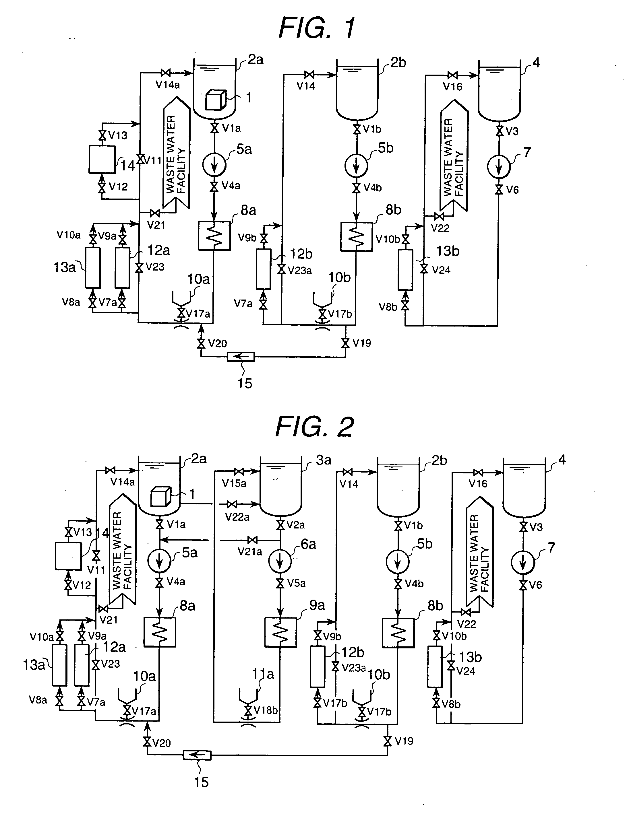
[0031] Fig. is a drawing representing the schematic configuration of a chemical decontamination apparatus of the present embodiment. This chemical decontamination apparatus comprises reducing decontamination tanks 2a and 2b, a washing tank 4 and a circulating pipe. The circulating pipe of the reducing decontamination tank 2a is provided with a pump 5a, heater 8a, chemical inlet 10a, cation resin column 12a, mixed bed resin column 13a, reducing agent decomposer 14 and others. The circulating pipe of the reducing decontamination tank 2b is equipped with a pump 5b, heater 8b, chemical inlet 10b, cation resin column 12b and others. The circulating pipe of the washing tank 4 is provided with a pump 7, mixed bed resin column 13b, etc.

[0032] Decontamination procedures will be described below:

[0033] Firstly, preparation for decontamination is made.

[0034] The reducing decontamination tanks 2a and 2b, and washing tank 4 and circulating pipe thereof are filled with wate...

embodiment 2

[0046] (Embodiment 2)

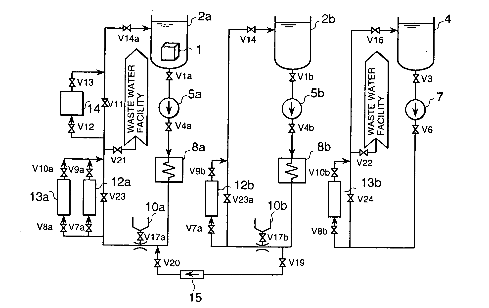
[0047]FIG. 1 shows the configuration of the present invention. This embodiment uses the step of oxidizing decontamination in addition to reducing decontamination to enhance the effect of decontamination. An oxidizing decontamination tank 3a and circulating pipe thereof are added to the configuration of embodiment 1. The circulating pipe of the oxidizing decontamination tank 3a are provided with a pump 6a, heater 9a and chemical inlet 11a.

[0048] Firstly, the following describes the preparation for operation:

[0049] The outlet valve V2a of oxidizing decontamination tank 3a, the outlet valve V5a of pump 6a and the return valve V15a of oxidizing decontamination tank 3a are opened. While circulating operation is performed using the pump 6a, temperature is raised to a predetermined level by a heater 9a. Then valve Vl8a is opened and oxidizing decontamination agent is supplied from the chemical inlet 11a until a predetermined concentration of oxidizing agent is reache...

embodiment 3

[0054] (Embodiment 3)

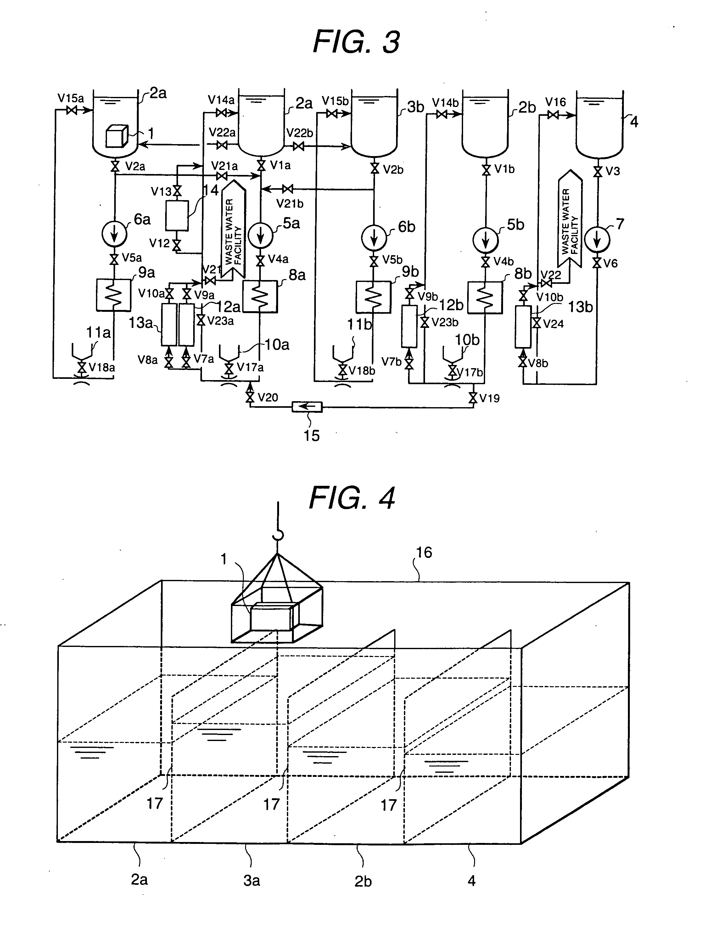
[0055]FIG. 1 shows the configuration of this embodiment. In this embodiment, the oxidizing decontamination tank 3b and circulating pipe thereof are added to the configuration of FIG. 2 to ensure that washing is carried out after oxidizing decontamination and reducing decontamination have each been carried out twice. The circulating pipe of the oxidizing decontamination tank 3b has the same configuration as that of the circulating pipe of the oxidizing decontamination tank 3a. A predetermined concentration and temperature of oxidizing agent are provided in the oxidizing decontamination tank 3b and circulating pipe thereof in the same manner as in the case of FIG. 2. Duplicated description will be omitted since the operation procedure is the same as that of the embodiments 1 and 2 except that the operation is started from the oxidizing decontamination.

[0056] The following describes the procedure of decontamination carried out in the order of oxidizing decontamina...


PUM


Abstract

A radioactive substance decontamination method and apparatus which decontaminates a metal member contaminated by radioactive substance in a short period of time. This apparatus has (1) multiple reducing decontamination tanks having different radiation control values; (2) a carrier for immersing the metal member into the multiple reducing decontamination tanks and a washing tank; (3) a tube for transferring into the second reducing decontamination tank the reducing decontamination agent in the first reducing decontamination tank; (4) a reducing agent decomposer for decomposing a component contained in the reducing decontamination agent of the reducing decontamination tank where the radiation control value is the highest out of the reducing decontamination tanks connected by the tube; and (5) a washing tank for washing the reducing decontamination agent deposited on the decontaminated metal member.

Description

BACKGROUND OF THE INVENTION [0001] 1. Field of the Invention [0002] The present invention relates to a radioactive substance decontamination method and radioactive substance decontamination apparatus. [0003] 2. Prior Art [0004] Chemical decontamination is a process of removing radioactive substance contained in the oxide film on the surface of an object to be decontaminated by repeating oxidizing and reducing treatment of the object to be decontaminated and by dissolving and removing said oxide film using oxidizing decontamination agent and reducing decontamination agent. [0005] A prior art of chemical decontamination is disclosed in Official Gazette of Japanese Patent Laid-Open NO. 105295 / 2000 where reducing decontamination is carried out using the reducing decontamination agent containing two or more components whereby the reducing decontamination agent is decomposed. Official Gazette of Japanese Patent Laid-Open NO. 510784 / 1997 also discloses a method for decomposing an organic a...

Claims


Application Information

Patent Timeline
Patent Type & Authority Applications(United States)
IPC IPC(8): G21F9/00G21F9/28
CPCG21F9/001
Inventor ANAZAWA, KAZUMISAKASHITA, MOTOAKINAGASE, MAKOTO
Owner HITACHI LTD
Why Eureka
Try Eureka