
Guide system for controlled manipulation of surgical instruments

a surgical instrument and guide system technology, applied in the field of surgical instruments, can solve the problems of increased scarring, increased pain, and potential infection, and change of resistance, and achieve the effect of reducing a number of openings and being easy to manipula

Inactive Publication Date: 2005-01-20
BAPTISTE REGINALD C +1
View PDF9 Cites 15 Cited by
  • Summary
  • Abstract
  • Description
  • Claims
  • Application Information

AI Technical Summary

Benefits of technology

[0008] Accordingly, it is an advantage of the present invention that a guide system is provided for controlled manipulation at a surgical site of a first instrument relative to a second instrument.
[0009] It is another advantage of the present invention that a guide system is provided for use with a pair of instruments that minimizes a number of openings required to perform an endoscopic surgical procedure.
[0010] Another advantage of the present invention is that a guide system is provided for use with a pair of instruments that can be readily manipulated by a surgeon.
[0011] Yet another advantage of the present invention is that a guide system is provided that maintains an appropriate working angle between a linear cutter stapler and a grasping forceps when excising tissue during an endoscopic surgical procedure.
[0012] The above and other advantages of the present invention are carried out in one form by a guide system for controlled manipulation at a surgical site of a first instrument relative to a second instrument. The first instrument includes an elongate flexible member interposed between a first effector and a first actuator, and the second instrument includes a shaft interposed between a second effector and a second actuator. The guide system includes a body having a first end and a second end. The body is configured to surround the shaft of the second surgical instrument such that the second effector extends from the first end and the second actuator extends from the second end. An articulating member is in longitudinal alignment with the body and is selectively moveable to cause an extension portion of the articulating member to move to an extended position transverse from the body. A sleeve is coupled to the extension portion and is configured to retain the elongate flexible member such that movement of the extension portion causes corresponding movement of the sleeve to adjust a working angle between the first and second effectors.
[0013] The above and other advantages of the present invention are carried out in another form by a forceps system for use in cooperation with a cutter stapler. The cutter stapler includes a stapler head, a stapler actuator, and a shaft interposed between the stapler head and the stapler actuator. The forceps system comprises a grasping forceps including a grasper, a grasper actuator, and an elongate flexible member interposed between the grasper and the grasper actuator. The forceps system further comprises a forceps guide system for controlled manipulation of the grasper relative to the stapler head. The guide system includes a body having a distal end and a proximal end. The body is configured to surround the shaft of the cutter stapler such that the stapler head extends from the distal end and the stapler actuator extends from the proximal end. An articulating member is in longitudinal alignment with the body. The articulating member has an activator portion and an extension portion pivotally coupled to the activator portion such that a pushing force applied to the activator portion causes the extension portion to exit from the slot and move to an extended position transverse from the body, and a pulling force applied to the activator portion causes the extension portion to move to a retracted position. A sleeve is coupled to the extension portion and retains the elongate flexible member such that movement of the extension portion causes corresponding movement of the sleeve to adjust a working angle between the grasper and the stapler head.

Problems solved by technology

For the patient, the multiple openings increase scarring, pain, and potential for infection.
In addition, the initial entry is fraught with danger.
This danger is due to the sudden change in resistance that occurs at the instant when the trocar's tip pierces the body.
If the trocar should suddenly penetrate the body too deep, underlying tissues and / or organs may be nicked, thus necessitating an unplanned for open surgery to repair the damaged tissue.
Accordingly, the creation of multiple openings exacerbates this danger.
Even when the trocars safely pierce the body, further problems can arise for the surgeon.
These problems include: restricted vision, no tactile perception, difficulty in handling the instruments, restricted mobility, and difficult hand-eye coordination.
The manipulation of multiple instruments through multiple openings is time consuming and tedious.
Moreover, it is difficult to appropriately grasp the tissue and only remove the desired amount due to the angle of attack of each of the instruments relative to one another.
Consequently, during such a surgery, the incision may not be straight, but rather curved, resulting in a longer incision and a greater quantity of tissue excised than is desired.

Method used


Image

  • Guide system for controlled manipulation of surgical instruments
  • Guide system for controlled manipulation of surgical instruments
  • Guide system for controlled manipulation of surgical instruments

Examples


Embodiment Construction

[0025] The present invention is described in connection with endoscopic surgical procedures and apparatus. However, the use of the term “endoscopic” used herein should not be construed to limit the present invention to instruments for use only in conjunction with an endoscopic tube. Rather, the present invention may find use in any procedure where access is limited to a small incision, including, but not limited to endoscopic and / or laparoscopic procedures.

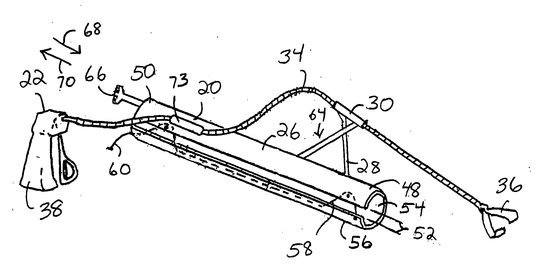
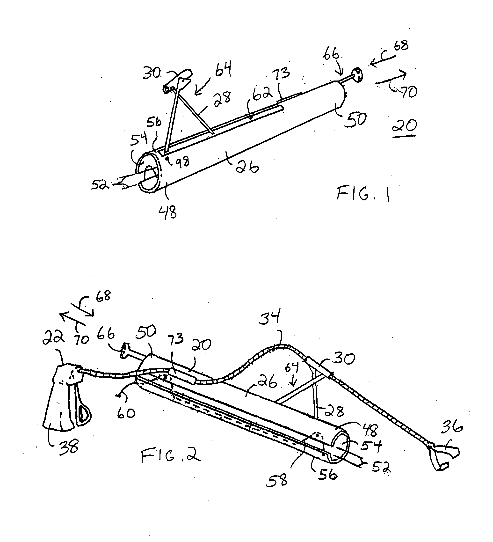
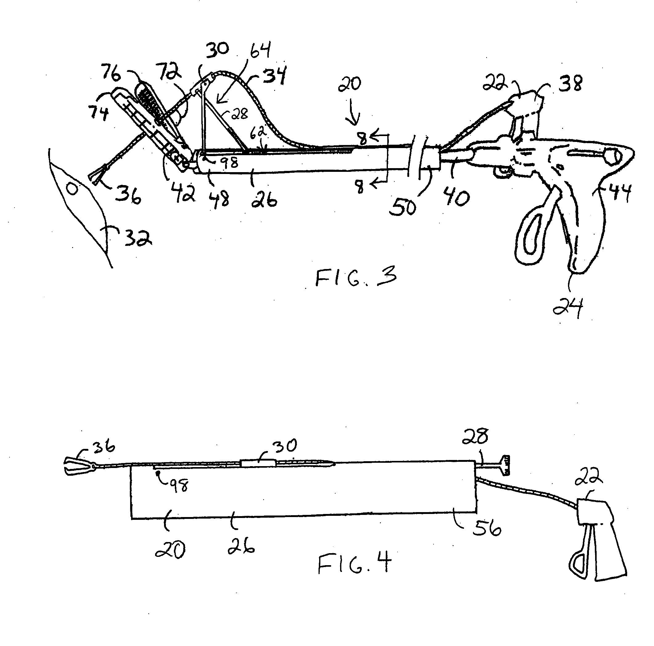
[0026]FIG. 1 shows a perspective view of a guide system 20 for controlled manipulation of a pair of surgical instruments in accordance with a preferred embodiment of the present invention. FIG. 2 shows a side perspective view of guide system 20 retaining a grasping forceps 22, and FIG. 3 shows an illustrative side view of guide system 20 in use with a linear cutter stapler 24. Guide system 20 includes a body 26, an articulating member 28 in longitudinal alignment with body 26, and a sleeve 30 coupled to articulating member 28.

[0...


PUM


Abstract

A guide system (20) enables controlled manipulation of a grasping forceps (22) relative to a cutter stapler (24). The guide system (20) includes a body (26) for surrounding a shaft (40) of the stapler (24), with a stapler head (42) and a stapler actuator (44) extending from opposing ends of the body (26). An articulating member (28) is in longitudinal alignment with the body (26) and is selectively moveable to cause an extension portion (64) of the member (28) to move to an extended position (82) transverse from the body. A sleeve (30), coupled to the extension portion (64), retains an elongate flexible member (34) of the grasping forceps (22). Movement of the extension portion (64) causes corresponding movement of the sleeve (30) to adjust a working angle (72) between a grasper end (36) of the grasping forceps (22) and the stapler head (42).

Description

TECHNICAL FIELD OF THE INVENTION [0001] The present invention relates to the field of surgical instruments for endoscopic procedures. More specifically, the present invention relates to a guide system for controlled manipulation of a grasping forceps relative to a cutter stapler instrument. BACKGROUND OF THE INVENTION [0002] For many surgical procedures, the method of choice has shifted from traditional open surgery to the use of less invasive means, sometimes referred to as endoscopic surgery. Endoscopic procedures entail the use of small diameter instruments such as cameras, graspers, forceps, retractors, dissectors, staplers, clamps, and so forth, inserted through small incisions in a body cavity or through cannulas inserted into the body. Endoscopic surgical procedures utilizing these small diameter instruments usually result in less pain, scarring, and recovery time for the patient, and a resultant reduction in health-care costs. [0003] An endoscopic surgical procedure to excis...

Claims


Application Information

Patent Timeline
Patent Type & Authority Applications(United States)
IPC IPC(8): A61B17/00A61B17/068A61B17/28A61B17/34
CPCA61B17/068A61B17/29A61B2017/3445A61B2017/00353A61B2017/2927A61B19/26A61B90/50
Inventor BAPTISTE, REGINALD C.SHER, SCOTT A.
Owner BAPTISTE REGINALD C
Learn More