Sealing element and holding-down clamp for a fuel injector

a technology of sealing element and holding clamp, which is applied in the direction of fuel injecting pump, machine/engine, mechanical apparatus, etc., can solve the problems of insufficient sealing, inability to use conventional sealing elements universally, and inability to ensure the sealing effect, etc., to achieve convenient assembly, improve the cooling effect of the valve body, and facilitate the effect of assembly

Inactive Publication Date: 2005-01-27
ROBERT BOSCH GMBH
View PDF6 Cites 32 Cited by
  • Summary
  • Abstract
  • Description
  • Claims
  • Application Information

AI Technical Summary

Benefits of technology

[0011] A sealing element according to the present invention may provide the advantage that the fuel injector may be installed into and removed from the cylinder head with no problem, because the sealing element is not under any prestress in the radial direction against the wall of the receiving bore of the cylinder head, so that the sealing element does not interfere with installation and removal. In particular, special tools are thus no longer necessary for installing and removing the fuel injector.
[0012] Another advantage may be that the prestress on the sealing element may be predetermined, thus lowering the demands regarding production accuracy. In addition, a fuel injector having the sealing element according to the present invention may be used universally.
[0013] The sealing properties of the sealing element may be independent of the location of the fuel injector and the receiving bore so that it is possible to compensate for an axial offset, for example, with no problem.

Problems solved by technology

One disadvantage of the sealing element described in German Published Patent Application No. 197 35 665 is that the prestress on the sealing element depends on the geometry and in particular on the diameter of the receiving bore.
Therefore, the conventional sealing element cannot be used universally but instead must be adapted specifically for each receiving bore.
In addition, the prestress on the sealing element cannot be adjusted, so the prestress varies due to aging or due to manufacturing tolerances and thus the seal may not be adequate.
In addition, the seal is exposed directly to the hot exhaust gases, which results in accelerated aging of the sealing ring.
Another disadvantage is that due to the radial prestress on the sealing element, there is a frictional force which counteracts an axial displacement of the sealing element.
This greatly interferes with both installation and removal as well as adjustment of the fuel injector.
Because of soiling deposits on the sealing element and aging of the sealing element, it may even be no longer possible to remove the fuel injector, or the sealing element may be destroyed during removal of the fuel injector.
One disadvantage of the fuel injector described in German Published Patent Application No. 197 43 103 is that the thermal insulation sleeve is prestressed in the area of the double layer of the sleeve between the nozzle body and the receiving bore.
This results in the problems mentioned above when installing or removing the fuel injector.
Another disadvantage is that the position of the fuel injector and the receiving bore is fixedly predetermined.
Because of manufacturing tolerances, the axis of the fuel injector introduced into the receiving bore does not in general exactly match the axis of a connection piece of a high-pressure fuel line.
The holding-down clamp described in Japanese Published Patent Application No. 8-312503 has the disadvantage that it acts on the fuel injector only in the axial direction.
In addition, there may be an unwanted load on the sealing element.
In the case of a sealing element designed as a sealing ring which is in contact with both the fuel injector and the wall of the receiving bore, shearing stresses build up peripherally during rotation of the fuel injector in the sealing ring, thus worsening the sealing properties of the sealing ring.
The disadvantages described above also apply to this holding-down clamp.

Method used


Image

  • Sealing element and holding-down clamp for a fuel injector
  • Sealing element and holding-down clamp for a fuel injector
  • Sealing element and holding-down clamp for a fuel injector

Examples


Embodiment Construction

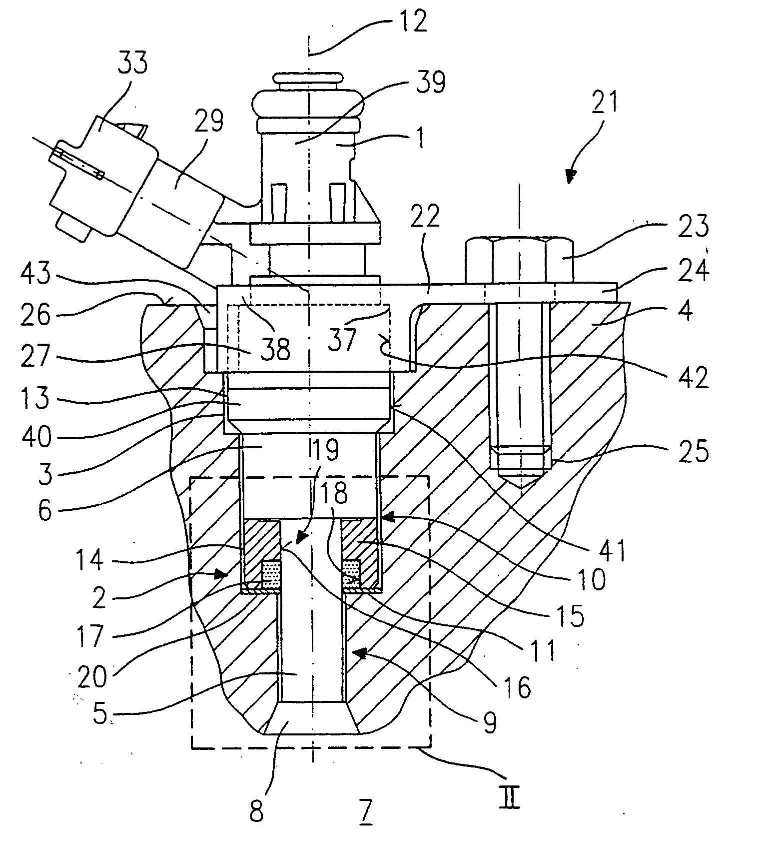
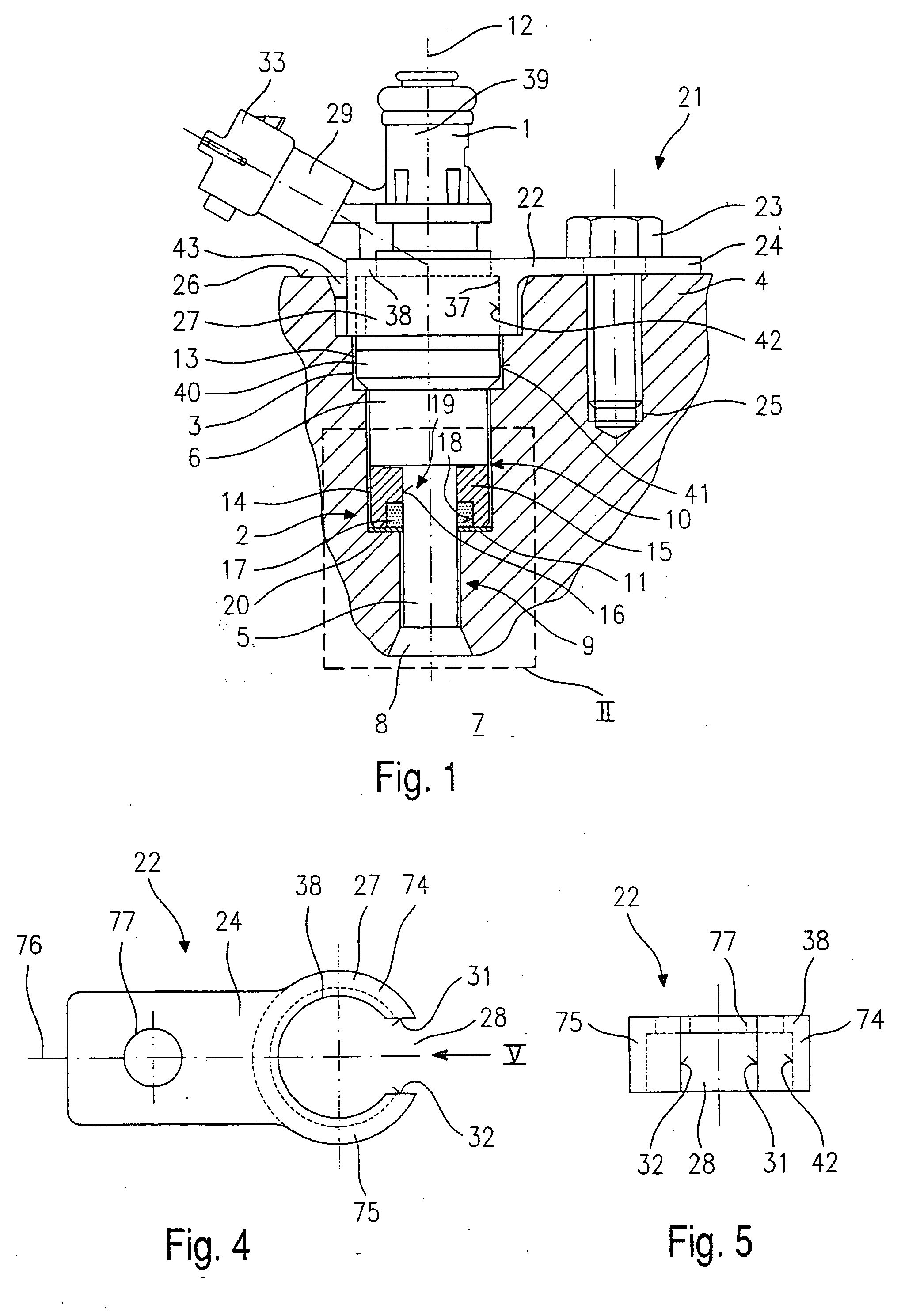
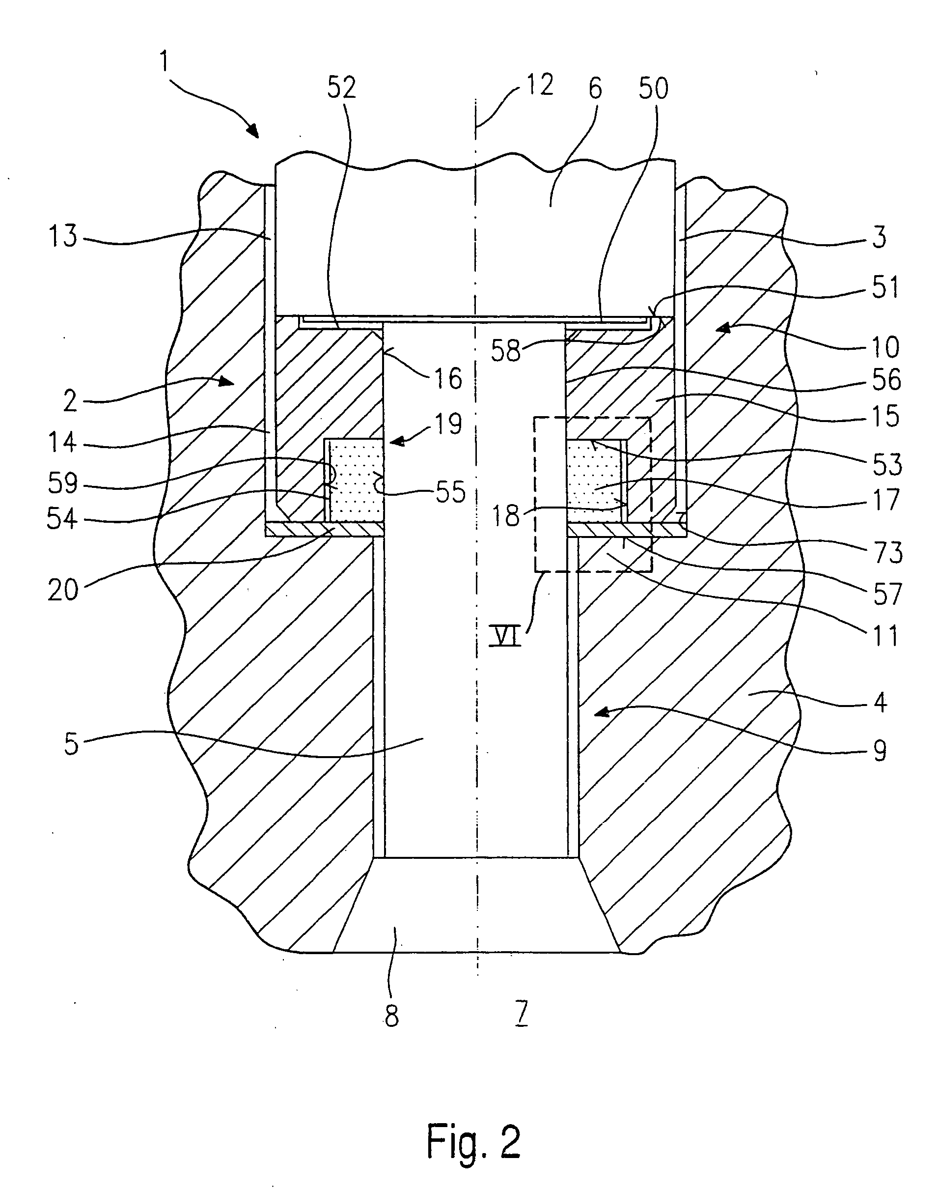
[0040]FIG. 1 illustrates a fuel injector 1 inserted into a receiving bore 3 in a cylinder head 4 having a sealing element 2 according to a first example embodiment. Fuel injector 1 has a nozzle body 5 connected to a middle part 6 of fuel injector 1. Nozzle body 5 has a fuel nozzle for injecting fuel into a combustion chamber 7 of the internal combustion engine, so that fuel enters combustion chamber 7 through a spray orifice 8 of cylinder head 4. Sealing element 2 surrounds nozzle body 5 on the periphery, the outside diameter of sealing element 2 at least essentially corresponding to the outside diameter of middle part 3, and the inside diameter of sealing element 2 corresponding at least essentially to the outside diameter of nozzle body 5. In addition, receiving bore 3 has a first section 9 of a smaller diameter and a second section 10 of a larger diameter. First section 9 and second section 10 are joined by a step 11 of receiving bore 3. The outside diameter of middle part 6 of f...


PUM


Abstract

A sealing element for a fuel injector insertable into a receiving bore of a cylinder head of an internal combustion engine for direct injection of fuel into a combustion chamber of the internal combustion engine includes a sealing element surrounding a nozzle body of the fuel injector peripherally. The sealing element includes a base body having an axial recess through which the nozzle body extends. The base body also has an annular recess which communicates with the recess and into which the sealing element is introduced. At a first contact face, the base body is in at least indirect contact with an end face of the fuel injector, and at a second contact face opposite the first contact face, the base body is at least in indirect contact with a step of the receiving bore.

Description

CROSS-REFERENCE TO RELATED APPLICATIONS [0001] This application is a division of U.S. patent application Ser. No. 10 / 048,671, which was the National Stage of PCT International Application No. PCT / DE01 / 02061, filed May 31, 2001, each of which is expressly incorporated herein in its entirety by reference thereto.FIELD OF THE INVENTION [0002] The present invention relates to a sealing element and a holding-down clamp. BACKGROUND INFORMATION [0003] German Published Patent Application No. 197 35 665 describes a sealing element. The sealing element is formed by a peripheral radial groove provided on a nozzle body of a fuel injector inserted into a receiving bore and a sealing ring inserted into the groove. The sealing ring is prestressed in the radial direction and is supported in the groove of the nozzle body as well as on the wall of the receiving bore. [0004] One disadvantage of the sealing element described in German Published Patent Application No. 197 35 665 is that the prestress on...

Claims


Application Information

Patent Timeline
Patent Type & Authority Applications(United States)
IPC IPC(8): F02F11/00F02F1/24F02M61/14F02M61/16F16J15/12
CPCF02M2200/858F02M61/14
Inventor KRAUSE, HEINZ-MARTINLAUTER, STEFAN
Owner ROBERT BOSCH GMBH
Why Eureka
Try Eureka