
Electro-active sensor, method for constructing the same; apparatus and circuitry for detection of electro-active species

a technology of electro-active sensors and methods, applied in the field of electro-active sensors, can solve the problems of inability to easily miniaturize, inability to easily configure sensors in multi-sensor arrays, and inability to achieve the effect of reducing the number of sensors

Inactive Publication Date: 2005-01-27
CALIFORNIA INST OF TECH
View PDF10 Cites 18 Cited by
  • Summary
  • Abstract
  • Description
  • Claims
  • Application Information

AI Technical Summary

Benefits of technology

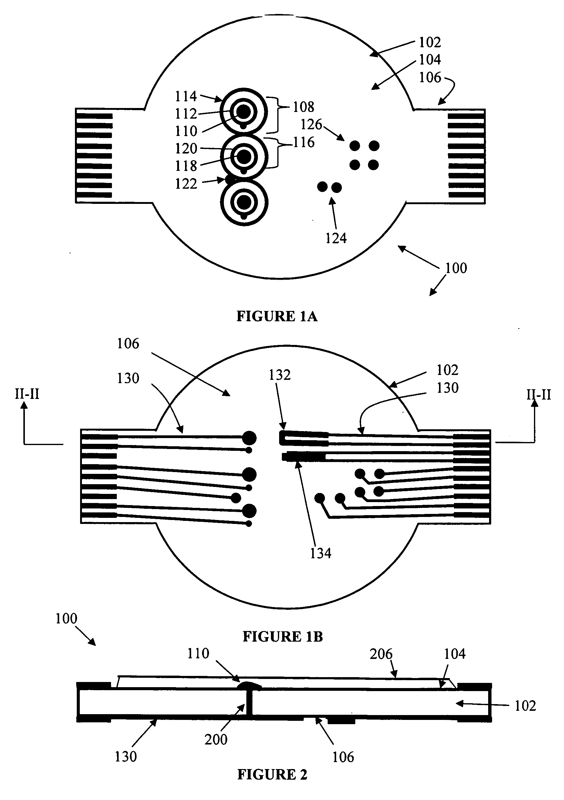
[0017] Additionally, the electro-active sensor further comprises a four-terminal conductivity sensor attached with the first side of the nonconductive platform, thereby allowing for a measurement of a conductivity of the solution.
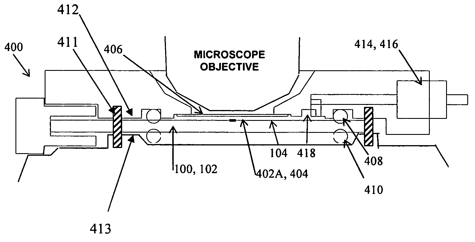
[0045] Additionally, a micro-fluidics system is attached with both the first sealable chamber and the second sealable chamber, allowing for control of the solution applied to each chamber.

Problems solved by technology

While functional, electrochemical sensors currently available suffer from several drawbacks.
Such sensors cannot be configured easily in a multi-sensor array, nor can they be readily miniaturized.
Additionally, because of their configuration, conventional sensors generally have short useful lives, with a long life typically being one month in natural waters and up to six months in drinking waters.
When used in bioreactors, the sensors typically have life expectancies of a few days.
Because of their short useful lives, traditional sensors are impractical for measuring water quality in applications where testing must take place for many months or years, such as on the ISS, and during a long trip to Mars.

Method used


Image

  • Electro-active sensor, method for constructing the same; apparatus and circuitry for detection of electro-active species
  • Electro-active sensor, method for constructing the same; apparatus and circuitry for detection of electro-active species
  • Electro-active sensor, method for constructing the same; apparatus and circuitry for detection of electro-active species

Examples


Embodiment Construction

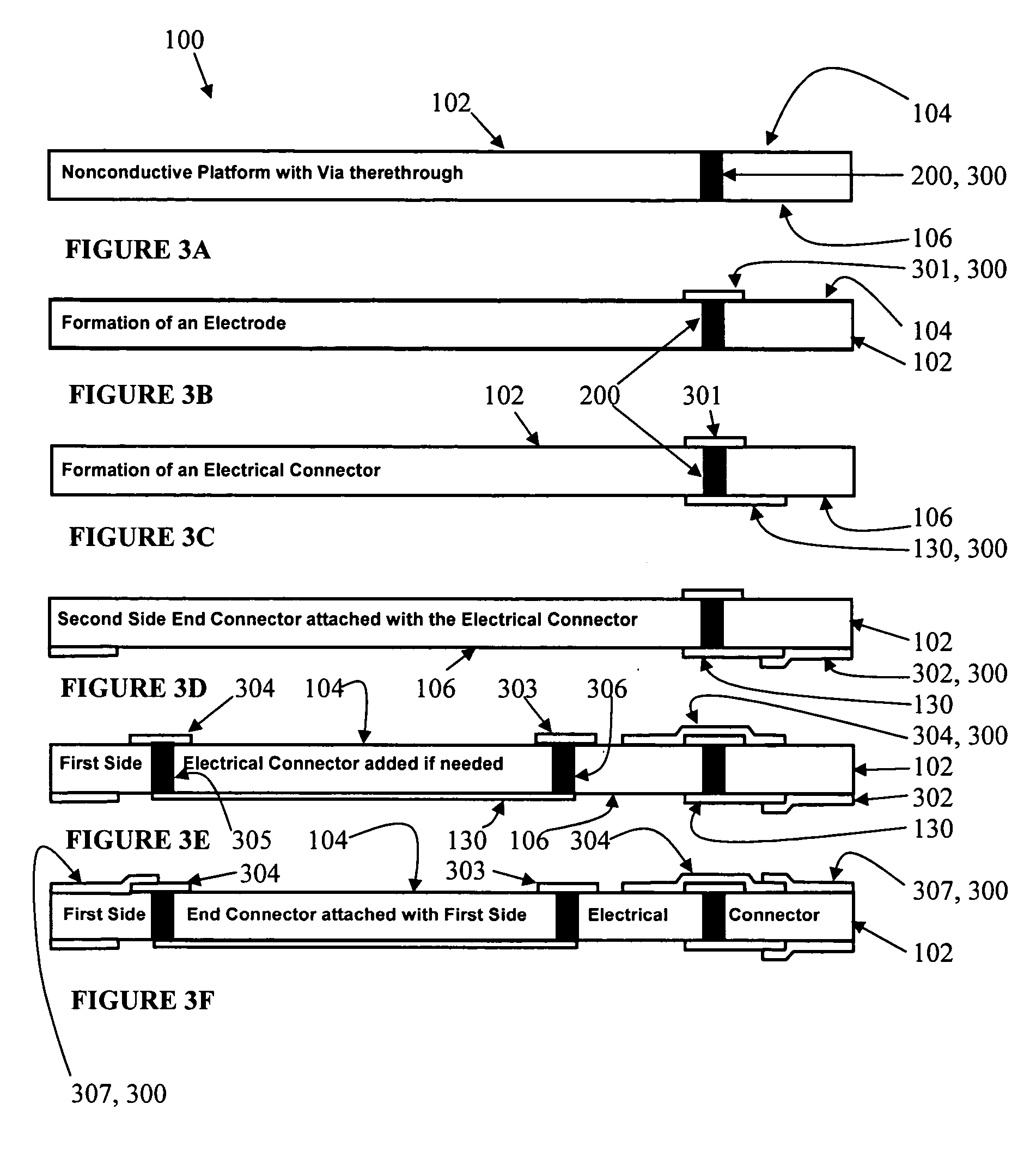
[0113] The present invention relates to electrochemical sensors, and more particularly, to a method and apparatus that are used to detect electro-active species in solution by measuring an electrochemical cell current as a voltage is scanned.

[0114] The following description, taken in conjunction with the referenced drawings, is presented to enable one of ordinary skill in the art to make and use the invention. Various modifications will be readily apparent to those skilled in the art, and the general principles defined herein may be applied to a wide range of aspects. Thus, the present invention is not intended to be limited to the aspects presented, but is to be accorded the widest scope consistent with the principles and novel features disclosed herein. Furthermore, it should be noted that unless explicitly stated otherwise, the figures included herein are illustrated qualitatively and without any specific scale, and are intended to generally present the concept of the present in...


PUM

PropertyMeasurementUnit
Fractionaaaaaaaaaa
Fractionaaaaaaaaaa
Fractionaaaaaaaaaa

Abstract

An electro-active sensor includes a nonconductive platform with a first electrode set attached with a first side of a nonconductive platform. The first electrode set serves as an electrochemical cell that may be utilized to detect electro-active species in solution. A plurality of electrode sets and a variety of additional electrochemical cells and sensors may be attached with the nonconductive platform. The present invention also includes a method for constructing the aforementioned electro-active sensor. Additionally, an apparatus for detection and observation is disclosed, where the apparatus includes a sealable chamber for insertion of a portion of an electro-active sensor. The apparatus allows for monitoring and detection activities. Allowing for control of attached cells and sensors, a dual-mode circuitry is also disclosed. The dual-mode circuitry includes a switch, allowing the circuitry to be switched from a potentiostat to a galvanostat mode.

Description

PRIORITY CLAIM [0001] This application is a non-provisional application, claiming the benefit of priority to provisional application Nos. 60 / 437,130 and 60 / 513,131, filed in the United States on Dec. 30, 2002 and Oct. 21, 2003, respectively, both titled “Electronic Tongue REDOX and Conductivity Sensors.”BACKGROUND OF THE INVENTION [0002] (1) Field of the Invention [0003] The present invention relates to electro-active sensors, and more particularly, to a electro-active sensor, method for constructing the same; apparatus, and circuitry that are used to detect electro-active species in solution. [0004] (2) Description of Related Art [0005] Electro-active sensors have long been known in the prior art. The sensors have been used in a myriad of applications, two examples of which include detecting low-levels of electrochemically active species found in drinking water used on the International Space Station (ISS) Alpha and detecting metabolic products produced by biofilms to better unders...

Claims


Application Information

Patent Timeline
IPC IPC(8): G01N27/403
CPCG01N27/4035
Inventor BUEHLER, MARTIN
Owner CALIFORNIA INST OF TECH
Learn More