Alternate polymer extrusion method with reduced drool

a technology of extrusion method and polymer, which is applied in the field of alternative polymer extrusion system, can solve the problems of not being able to accurately measure plastic or other materials, not being able to use the extruder as a positive shut-off device, and being close to what the patented system can do, so as to achieve the effect of increasing the speed of the gear pump, rapid development of the needed higher pressure, and increasing the pressur

Inactive Publication Date: 2005-01-27
DAVIS STANDARD
View PDF10 Cites 11 Cited by
  • Summary
  • Abstract
  • Description
  • Claims
  • Application Information

AI Technical Summary

Benefits of technology

In one preferred embodiment of the alternate polymer extrusion system having the improvement in accordance with this invention, a controller is coupled to the first and second gear pumps to vary the speed and hence the throughput of the first and second gear pumps. The controller is programmable to vary the speed and timing of the first and second gear pumps to compensate for the effect of the pinch points. The movement of melt past each pinch point occurs more slowly than would occur in the absence of the pinch point by virtue of compression of the melt with increased pressure developed between the gear pump and the pinch point. The controller is programmed to increase gear pump speed to more quickly develop the needed higher pressure. With slowing or halting of each gear pump, the decrease in the movement of melt past each pinch point is slower than would occur in the absence of the pinch point. By virtue of expansion of the melt with decreasing pressure between the gear pump and the pinch point, melt continues to move past the pinch point. The controller slows the gear pump more rapidly or reverses it to compensate for this effect as well.
In one preferred embodiment, a sensor measures a dimension of an extrudate during the extrudate's production. The sensor is connected to the controller. Lag time programming of the controller associates a lagging dimensional change with a preceding change of speed of at least one of the gear pumps. This permits repetitive gear pump speed changes being compensated by the controller to effect reduction or elimination of the dimensional anomaly in subsequent gear pump speed changes. Put another way, the system determines when a gear pump speed change will have a dimensional effect and assures that corrective action is made at the appropriate time.
In a further preferred embodiment of the invention, a controller controls a number of dimension-affecting parameters such as gas pressure differential between the interior and exterior of a hollow extrudate and puller speed, as well as the gear pump speeds. Compensatory dimension controlling corrections can be made in one or more of these parameters to compensate for and avoid the dimensional effects from increased melt compression as previously described.

Problems solved by technology

However, when the concepts of that '814 patent were extended to different sizes and types of tubing and different polymers, several problems arose.
As explained in the '814 patent, other methods can alternate the constituents and make certain configurations, but do not come close to what the patented system can do.
What it cannot do is meter the plastic or other material accurately.
A further problem is that an extruder is not a positive shut-off device.
Unfortunately, this is only true in the case where the two polymers have identical durometers, elasticity, and other physical characteristics.
It can never, however, be zero, and if nothing is done, that volume will “drool” out into the melt stream even when the melt pump for that layer is stopped.
This is unsatisfactory for applications of alternate polymer tubing in which one of the chief qualities being sought in the tubing was as short as possible a transition from one polymer to another of perhaps two to four inches.

Method used


Image

  • Alternate polymer extrusion method with reduced drool
  • Alternate polymer extrusion method with reduced drool
  • Alternate polymer extrusion method with reduced drool

Examples


Embodiment Construction

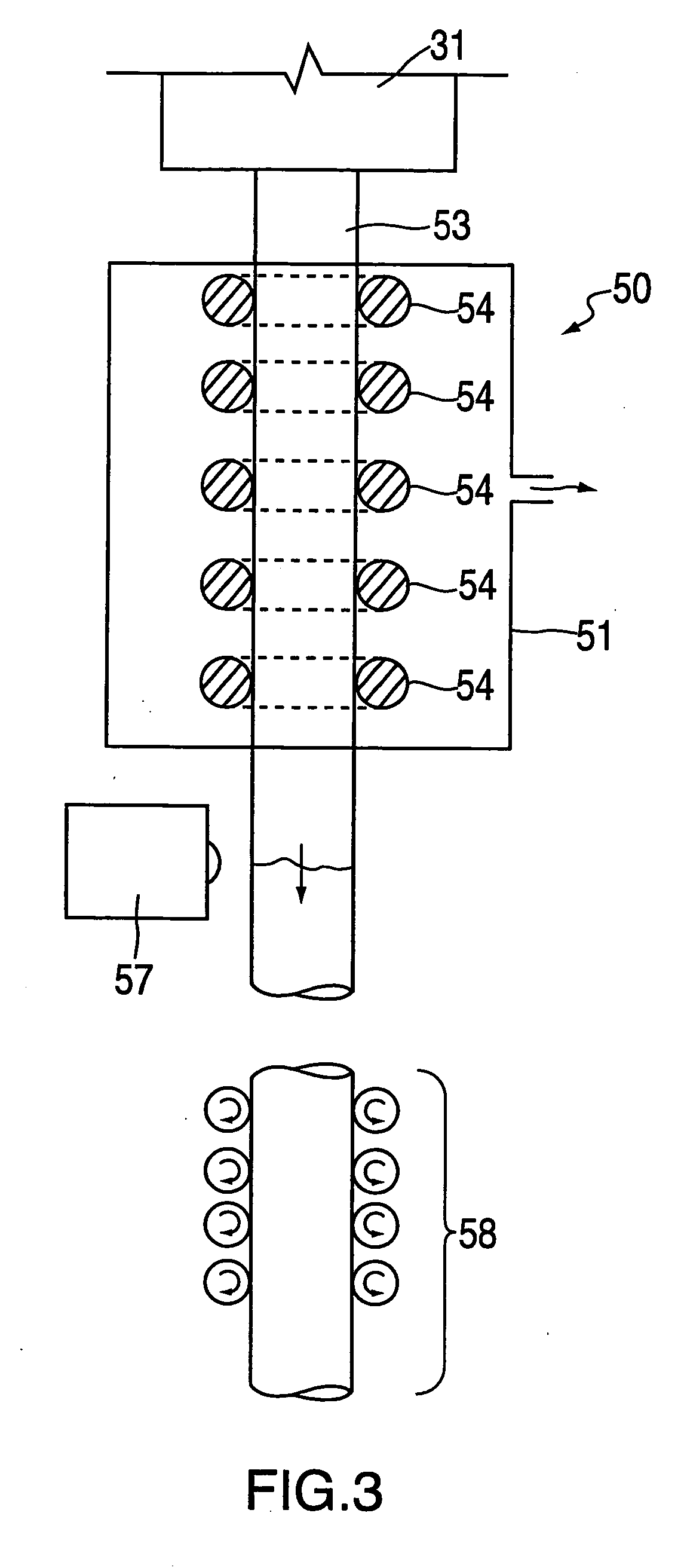
Constrictions to Prevent Drool

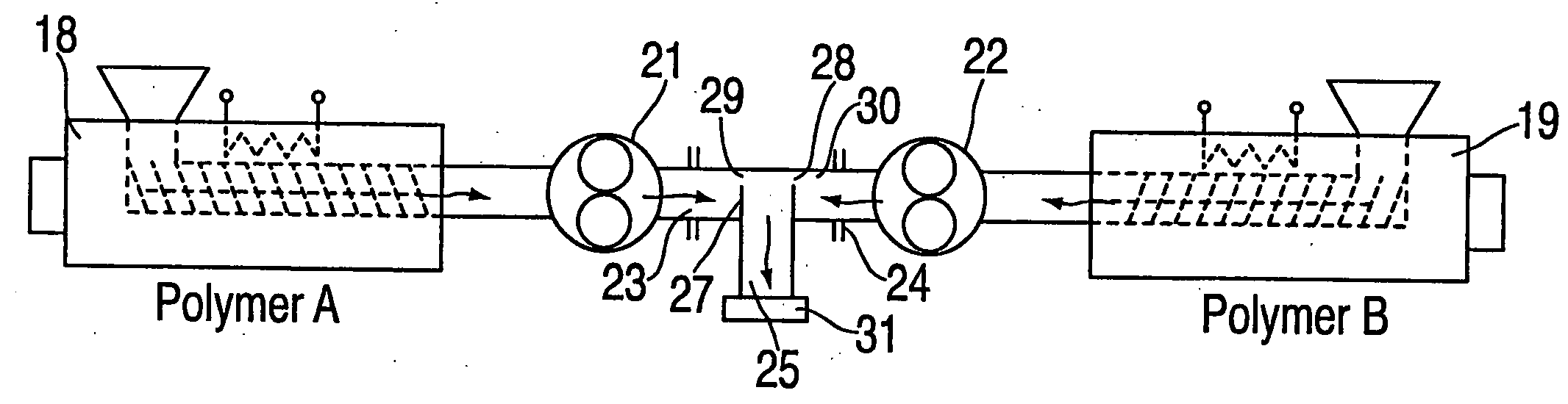
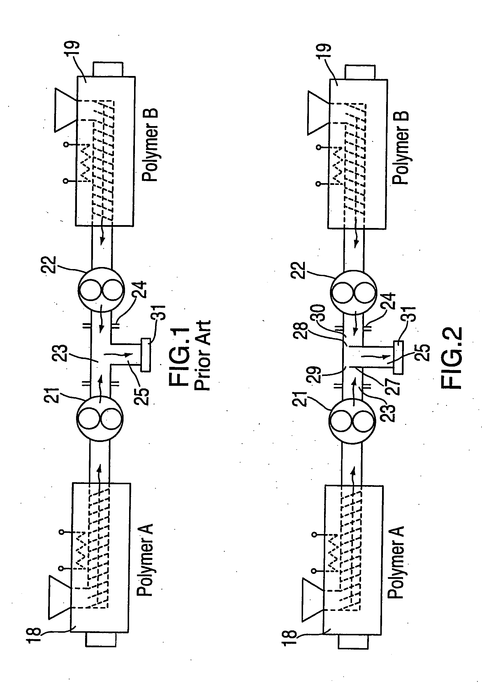
The principle of this invention can be described using the diagrammatically illustrated system shown in FIGS. 1 and 2. FIG. 1 is representative of the practice of the alternate polymer system prior to the present improvement. A first extruder 18, shown on the left, supplies a melt of a polymer A to a first gear pump 21. A second extruder 19, shown on the right, supplies a melt of a polymer B to a second gear pump 22. If one has a plastic stream coming in from the left gear pump 21 along the left branch 23 for a period, and suddenly stops the gear pump 21 and starts the gear pump 22 feeding the right branch 24, then one is going to find that the plastic in the left branch will drool out for quite a long time. This will occur pretty much until the left branch 23 is emptied of plastic melt. This effect is aggravated by Bernouilli's principle, which provides that a fluid flow past an orifice will create a suction.

Referring to FIG. 2, there has been erec...


PUM

PropertyMeasurementUnit
speedaaaaaaaaaa
dimensionaaaaaaaaaa
pressureaaaaaaaaaa

Abstract

An alternate polymer extrusion method and system reduces “drool” effects that detract from precise control over the content of two or more materials in an extrudate along its length. In the system, two or more extruders direct melt to two or more gear pumps. Control of the speed of the gear pumps controls the amount of each material emergent from the pumps, proceeding to a convergence in the paths from the pumps and thence to a die. Melt in each path between each pump and the convergence tends to expand and drool into the convergence as its associated pump is slowed and stopped. To prevent this, in the die, a constriction in each path just upstream of the convergence greatly reduces drool past that point by requiring a much greater pressure to force the melt past the constriction. The increased pressure required increases compression and expansion of the melt between the pump and the construction as a pump starts or increases in speed, on one hand, and stop or decreases in speed, on the other hand. Compensatory pump speed changes are made to counter this effect.

Description

FIELD OF THE INVENTION This invention relates to alternate polymer extrusion systems, and more particularly to alternate polymer extrusion systems for more precisely varying the content of material along the length of an extrudate. BACKGROUND OF THE INVENTION The above-referenced '814 patent describes a system for altering the content of an extrudate along the length of the extrudate using speed controlled gear pumps (sometimes referred to herein as “melt pumps”) to meter melt flowing in two or more extrusion lines that converge in a single die. The expressions “alternate polymer extrusion,”“alternate polymer extrusion system,” and the like are not intended to limit the invention described herein solely to polymers, but to refer to extrusion of two or more materials that may include, for example, rubber or another material. Also, alternate polymers and polymers A and B as referred to herein may refer to the same polymers, but having, e.g., different durometers, colors, or other p...

Claims


Application Information

Patent Timeline
Patent Type & Authority Applications(United States)
IPC IPC(8): B29C47/06B29C48/90B29C48/92
CPCB29C47/0016B29C2947/92885B29C47/0023B29C47/003B29C47/065B29C47/261B29C47/903B29C47/907B29C47/92B29C2947/92019B29C2947/92114B29C2947/92123B29C2947/92133B29C2947/92209B29C2947/92361B29C2947/92514B29C2947/9259B29C2947/926B29C2947/92647B29C2947/92704B29C2947/92723B29C2947/92857B29C47/0021B29C48/92B29C2948/92209B29C2948/92704B29C48/06B29C48/08B29C48/09B29C48/12B29C48/21B29C48/2692B29C48/336B29C48/903B29C48/904B29C48/907B29C2948/92019B29C2948/92114B29C2948/92123B29C2948/92133B29C2948/92361B29C2948/92514B29C2948/9259B29C2948/926B29C2948/92647B29C2948/92723B29C2948/92857B29C2948/92885B29B7/72
Inventor HARRIS, HOLTON E.
Owner DAVIS STANDARD
Why Eureka
Try Eureka