Video processor for endoscopy

a video processor and endoscope technology, applied in the field of video processors for endoscopes, can solve problems such as compatibility problems, adaptation problems, and inability to accept phase shifts at the processor, and achieve good immunity to interferen

Inactive Publication Date: 2005-01-27
TOKENDO
View PDF9 Cites 65 Cited by
  • Summary
  • Abstract
  • Description
  • Claims
  • Application Information

AI Technical Summary

Benefits of technology

[0037] a remote auxiliary circuit comprising second signal processing means connected to the first signal processing means through a low impedance electrical link providing good immunity to interference, the second signal processing means comprising means for generating from said raw video brightness and color signals at least one useful video signal according to an international standard.

Problems solved by technology

Transferring the color CCD sensor into the head of an endoscopic camera or the distal end of a videoendoscopic probe inevitably leads to an unacceptable phase shift at the processor between the sampling clock and the incident electrical signal, due to the length of the electrical links between the sensor and the video processor and characteristics of the interface circuit that may be associated with the sensor.
The considerations mentioned above show that connection of an endoscopy camera or a videoendoscopic probe to a video processor housed in an external box causes adaptation problems due to the need to compensate for synchronization delays induced by the probe or camera CCD sensor interface circuit, and by the electrical cable connecting the interface circuit to the video processor with which the CCD sensor is associated.
If the external box is always associated with the same model of endoscopic camera, there is an inter-changeability problem imposing that the length of the umbilical cable of cameras shall always be exactly the same.
For example, if the external box is associated with a range of videoendoscopic probes with different lengths (as described in U.S. Pat. No. 4,539,568), there will be a compatibility problem requiring the integration of a specific delay device into the connection box or into the control handle of the probe, acting on the fast clocks generated by the video processor and transmitted to the distal CCD sensor.
In any case, the use of an external video processor has another technical disadvantage concerning risks of interference of the electrical signal generated by the CCD sensor and transmitted to the video processor.
Transport of the electrical signal generated by the CCD sensor is difficult due to its low intrinsic signal / noise ratio, and also due to its wide pass-band and its low power requiring a link with a high impedance that does not help to give good immunity to interference.
Unfortunately, the intrinsic size of a video processor is incompatible with the available volume in a camera head and in a small probe handle.

Method used


Image

  • Video processor for endoscopy
  • Video processor for endoscopy
  • Video processor for endoscopy

Examples


Embodiment Construction

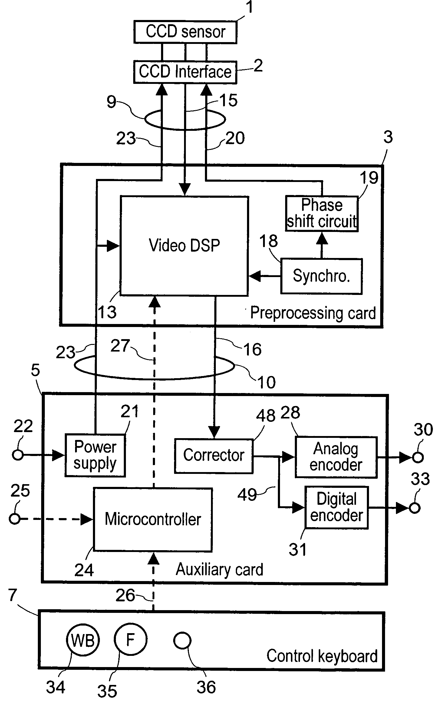
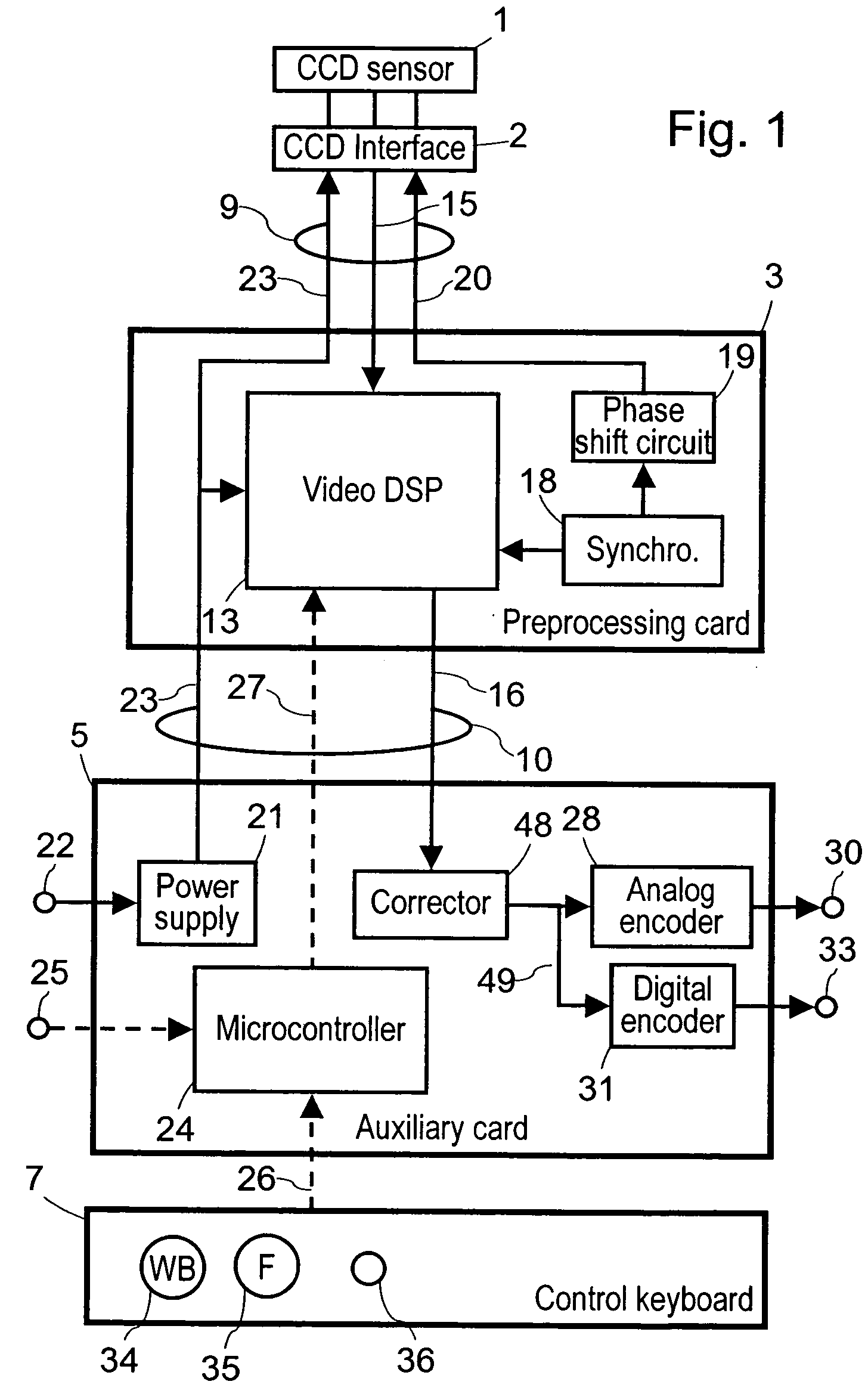
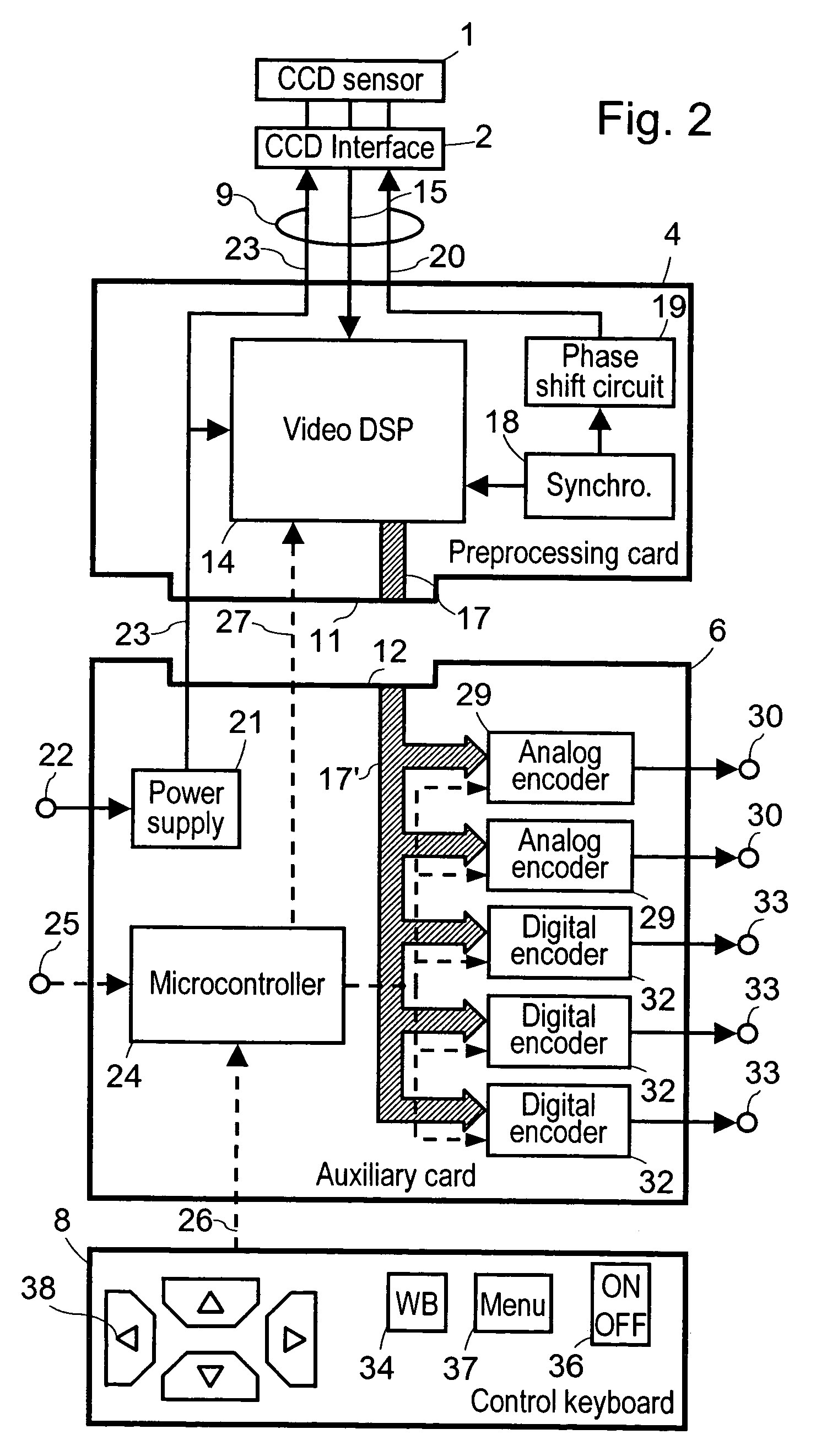
[0082] This invention is designed to integrate a video processor into a small videoendoscopic probe or endoscopy camera.

[0083] This objective is achieved by physically separating the signal processing functions themselves from the auxiliary functions of a video processor on two cards connected to each other through an electrical link. The card on which the signal processing functions are implanted is as small as possible so that it can fit into an endoscopy camera head or into the control handle of a videoendoscopic probe.

[0084] The first of these two cards is connected to the CCD sensor through an electrical link in which there is no risk of a break in the continuity. It is intended to be housed as close as possible to the CCD sensor and therefore preferably either in the handle of a videoendoscopic probe or in the head of an endoscopy camera. To achieve this, and in order to minimize its size, it only contains the minimum electronic means necessary to perform the following funct...


PUM


Abstract

A video processor for endoscopic camera or for videoendoscopic probe associated with a color video sensor, the video processor comprising: a signal preprocessing circuit designed to be remotely connected to the video sensor through an electrical link without any intermediate connection device, the preprocessing circuit comprising a first signal processor for generating from image signals output by the video sensor raw video signals comprising a brightness signal and a color signal, these signals being not usable directly because they are phase shifted and are noisy due to synchronization residues, and a synchronizing circuit for synchronizing the video sensor and the first signal processor; and a remote auxiliary circuit comprising a second signal processor connected to the first signal processor through a low impedance electrical link providing good immunity to interference, the second signal processor generating from said raw video brightness and color signals at least one useful video signal according to an international video standard.

Description

BACKGROUND OF THE INVENTION [0001] This invention relates to a video processor for a videoendoscopic probe or a video camera connectable to an endoscope. [0002] It is particularly but not exclusively applicable to endoscopy for medical purposes and endoscopy for industrial purposes. [0003] The terms endoscope or fiberscope refer to a flexible or rigid probe designed to be inserted into an obscure cavity so that its user can observe the image of a target located in the cavity through an ocular. For this purpose, the probe integrates a target illumination device and an optical device supplying an image of the target to the user. The optical device comprises a distal objective, an image transport device that is either inherently rigid composed of a series of lenses, or inherently flexible composed of a bundle of ordered optical fibers, and a proximal ocular in which the user can observe the image of the target. The illumination device generally comprises a bundle of illumination fibers...

Claims


Application Information

Patent Timeline
Patent Type & Authority Applications(United States)
IPC IPC(8): A61B1/04
CPCA61B1/04
Inventor ROVEGNO, JEAN
Owner TOKENDO
Why Eureka
Try Eureka