Controlled surface wave image velocimetry

Inactive Publication Date: 2005-01-27
UNIV OF IOWA RES FOUND
View PDF2 Cites 40 Cited by
  • Summary
  • Abstract
  • Description
  • Claims
  • Application Information

AI Technical Summary

Problems solved by technology

For those situations, the available techniques are either inaccurate or impossible to use.
Specifically, there are no means to measure free-surface

Method used


Image

  • Controlled surface wave image velocimetry
  • Controlled surface wave image velocimetry
  • Controlled surface wave image velocimetry

Examples


Embodiment Construction

A. Overview

For a better understanding of the invention, exemplary embodiments will now be described in detail. These are examples of forms the invention can take, and are not inclusive or exclusive. These examples are illustrations of some forms the invention can take and are intended to assist in an understanding of the invention.

Reference in this description will sometimes be made to the drawings. Reference numbers or letters may sometimes be used to identify certain parts and locations in the drawings. The same reference numbers or letters will be used to indicate the same or similar parts or locations throughout the drawings, unless otherwise indicated,

B. Exemplary System

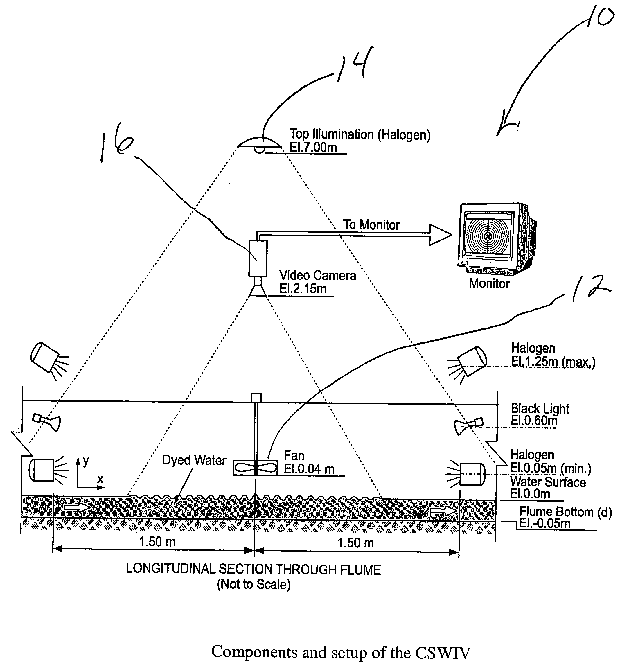
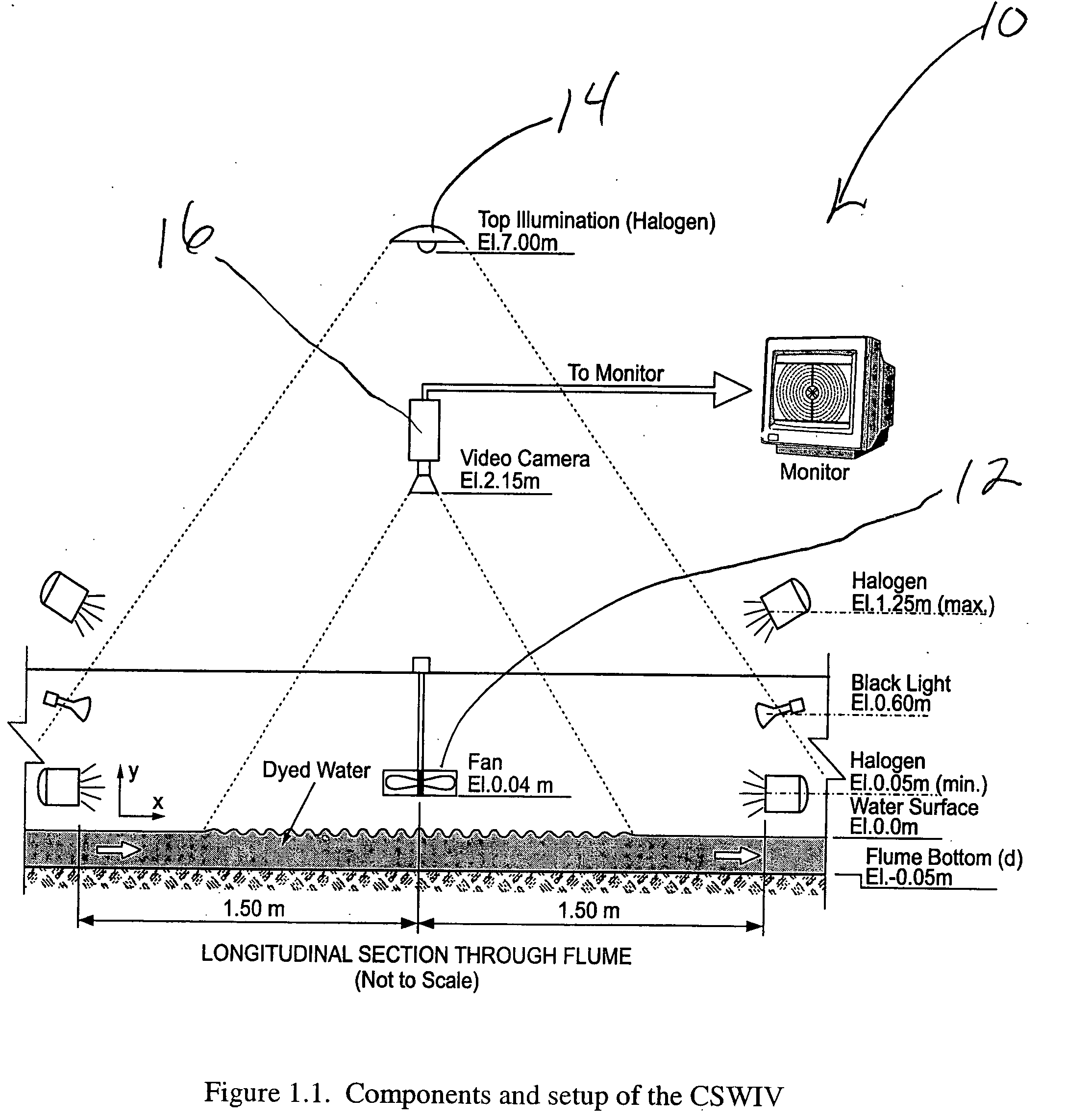
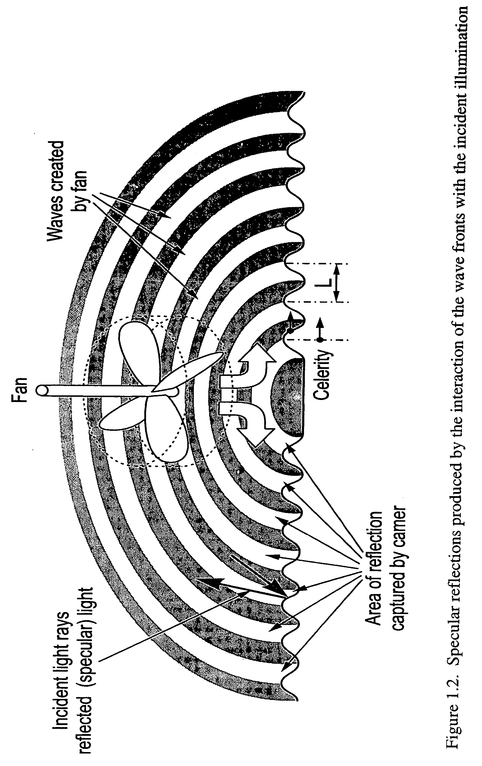
One exemplary embodiment includes a fan positioned above the surface of the flow. The fan is operated and positioned to produce a controlled pattern of surface waves. Preferably the pattern emanates in all directions in the plane of the fluid surface. Illumination (natural or artificial) of the surface ar...


PUM


Abstract

An apparatus, method, and system of gathering information useful to derive the velocity of the free surface liquid flow in an open channel flow. The method involves recording successive images of controlled surface waves on the open channel flow with sufficient resolution to derive spread of fronts of the controlled surface waves, using image velocimetry to derive celerity of controlled surface waves, and inferring the velocity vector field of the underlying liquid flow using wave theory elements or calibrations. An apparatus according to one aspect of the invention uses an artificial nonintrusive mechanism to set up the controlled surface waves, uses artificial light to illuminate the controlled surface wave to accentuate its affronts, digital camera to capture the successive images. Software can be used to utilizes image velocimetry and to infer the velocity vector field.

Description

I. BACKGROUND OF THE INVENTION A. Field of the Invention The present invention relates to a method, apparatus and system to measure the total free-surface velocity vector field of a moving body of liquid in field and laboratory conditions. B. Problems in the Art A need exists for effective and efficient nonintrusive measurement or monitoring of velocities of free surface flows. Benefits exist in at least industrial, environmental, and research contexts. A variety of methodologies have been developed towards this end for measurement of flow velocities in a body of moving liquid. However, many are labor intensive and cumbersome. Many are usable only in a narrow set of circumstances. Many also lack accuracy or reliability. Most of the existing methods cannot measure the velocity at the free surface. Recently, some fairly technical systems have been developed for measurement of free-surface velocities. Examples are well known in the art and include particle image velocimetry (PIV)...

Claims


Application Information

Patent Timeline
IPC IPC(8): G01F1/00G01F23/292G06K9/00
CPCG01F23/292G01F1/002
Inventor MUSTE, MARIANCREUTIN, JEAN-DOMINIQUESCHONE, JORG
Owner UNIV OF IOWA RES FOUND
Why Eureka
Try Eureka